4 adjustment of the output voltage zero (r81), Adjustment of the output voltage zero (r81) -2 – KEPCO BIT 4882F User Manual
Page 22
3-2
BIT 4882 100203
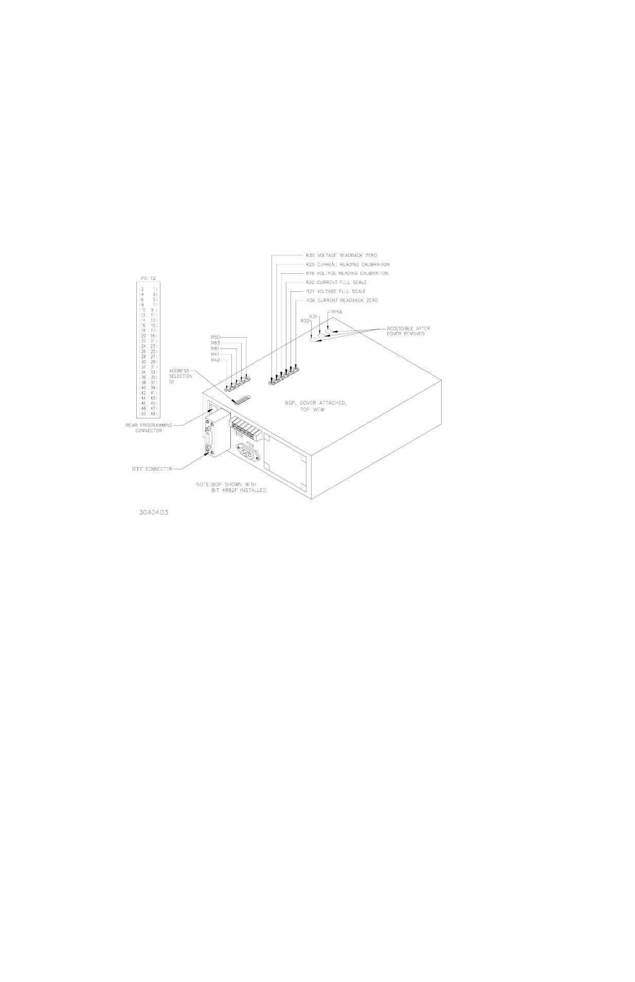
FIGURE 3-1. BOP POWER SUPPLY, INTERNAL CALIBRATION CONTROL LOCATIONS
3.4
ADJUSTMENT OF THE OUTPUT VOLTAGE ZERO (R81)
1. Without a load connected to the BOP output, connect a DVM between the FRONT PANEL
SENSING TERMINALS of the BOP Power Supply.
2. Turn the BOP Power Supply “ON”, program the BOP Power Supply to ZERO VOLTAGE
AND MAXIMUM CURRENT LIMIT.
• If using SCPI send
VOLT 0;CURR MAX
• If using CIIL send
FNC DCS:CH1 VOLT 0 with CURL .5
3. Locate Eo COMP AMP ZERO control R81 (see Figure 3-1, refer to Table 3-1).
4. Adjust control R81 for zero, ±100 microvolts.
3.5
ADJUSTMENT OF THE FULL SCALE OUTPUT VOLTAGE (R21)
1. Program the BOP Power Supply for PLUS FULL SCALE VOLTAGE.
• If using SCPI send
VOLT MAX;CURR MAX
• If using CIIL send
FNC DCS:CH1 VOLT xx with CURL .5
where
xx
is the maximum rated output voltage of the BOP.