4 adjustment of the output voltage zero (r81), Adjustment of the output voltage zero (r81) -2 – KEPCO BIT 232F User Manual
Page 18
3-2
BIT 232 022800
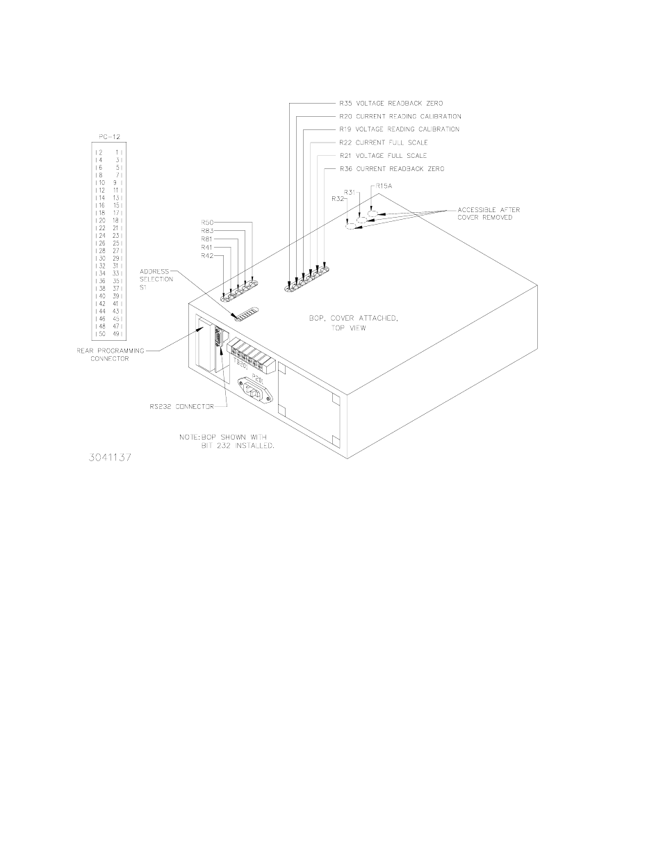
FIGURE 3-1. BOP POWER SUPPLY, INTERNAL CALIBRATION CONTROL LOCATIONS
3.4
ADJUSTMENT OF THE OUTPUT VOLTAGE ZERO (R81)
1. Without a load connected to the BOP output, connect a DVM between the FRONT PANEL
SENSING TERMINALS of the BOP Power Supply.
2. Turn the BOP Power Supply “ON”, program the BOP Power Supply to ZERO VOLTAGE
AND MAXIMUM CURRENT LIMIT.
3. Locate Eo COMP AMP ZERO control R81 (see Figure 3-1, refer to Table 3-1).
4. Adjust control R81 for zero, ±100 microvolts.
3.5
ADJUSTMENT OF THE FULL SCALE OUTPUT VOLTAGE (R21)
1. Program the BOP Power Supply for PLUS FULL SCALE VOLTAGE.
2. Locate VOLTAGE FULL SCALE control R21 (see Figures 2-1 and 3-1, refer to Table 3-1).
3. Adjust control R21 for FULL SCALE VOLTAGE, ±1 millivolt.
4. Program the BOP Power Supply for MINUS FULL SCALE. The output should be NEGATIVE
FULL SCALE ±0.024% (±1 LSB).