Caution, Pvcheck – HT instruments PVCHECK User Manual
Page 37
PVCHECK
EN - 35
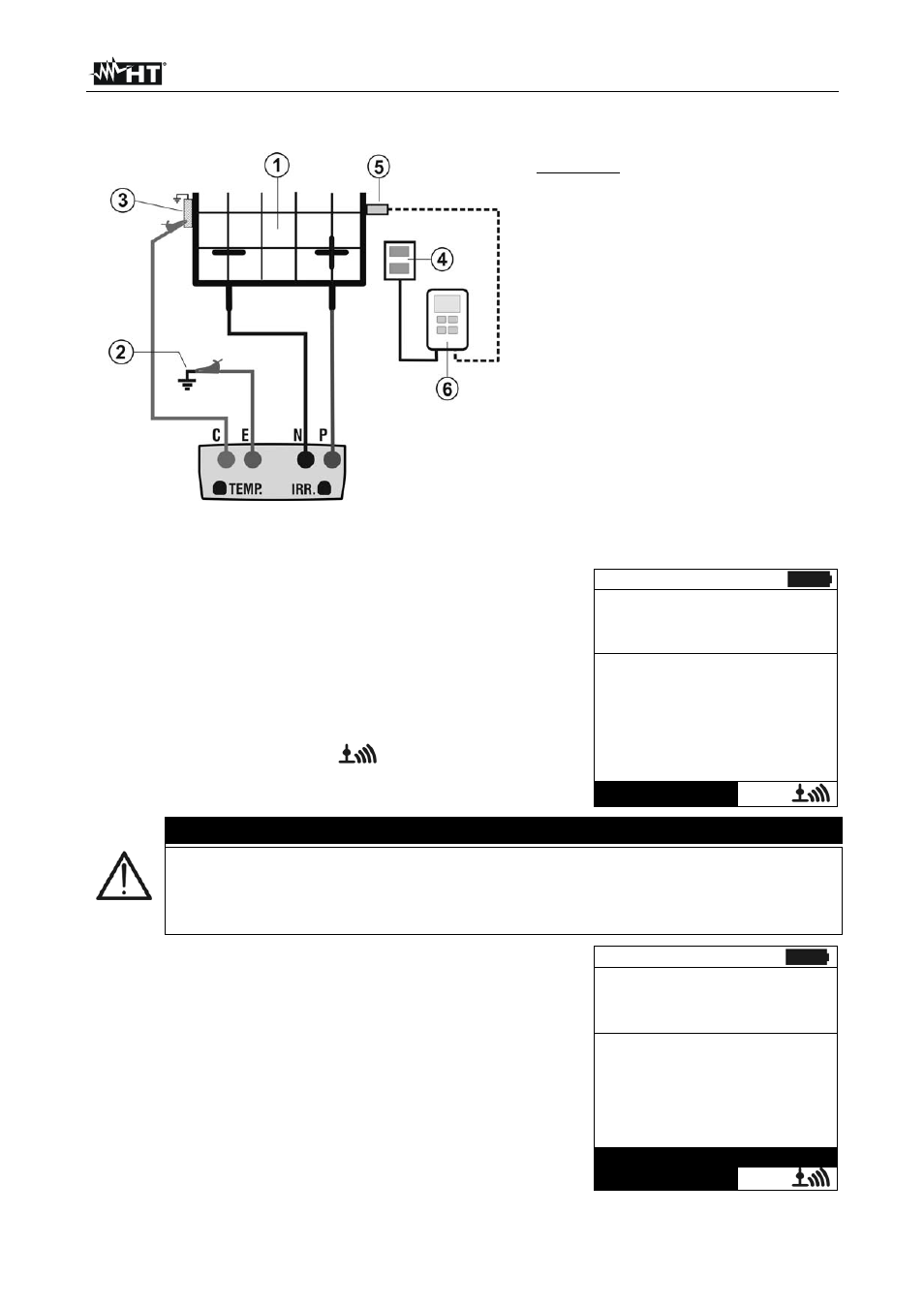
Fig. 8: Connection for IVCK test with direct irradiance measurement
CAPTION:
E: Green
cable
C: Blue
cable
P: Red
cable
N: Black cable
1. PV module/string
2. Main system earthing
3. Earthed metal structure in the
system
4. Reference cell for irradiance
measurement
5. Temperature
sensor
(if
required)
6. Unità
remota
SOLAR-
02Remote unit SOLAR-02
Fig. 9: Connection for IVCK test with irradiance measurement through SOLAR-02
14. In the initial screen of IVCK mode, the following values
are displayed in real time:
Module type of module being tested
Vdc value of output voltage from module/string
Irr irradiance (from a direct measurement or
SOLAR-02 connected via RF)
Tc modulo temperature (in MAN or AUX mode) and
the relevant measuring mode, or “- - -” in AUTO mode
In case, the symbol “
” of RF connection with
SOLAR-02
15/05/12 15:34:26
M o d u l e :
S U N P W R 3 1 8
V d c :
5 4 8 . 0
V
I r r
:
8 5 6 W / m 2
T c
:
A u t o ° C
V o c , I s c :
R i ( 1 0 0 0 V )
- - -
M
R p e ( C a l )
- - -
Selezione
I V C K
CAUTION
Upon pressing the GO/STOP key, different error messages can be displayed
by the instrument (see § 6.6) and, therefore, the test cannot be started. Check
and eliminate, if possible, the problem causing the error message before going
on with the test.
15. Press GO/STOP to start the test. In case no error
conditions occur, the instrument displays the message
“Measuring…” and the measure of open-circuit voltage
between the terminals P and N and of short-circuit current
(for Isc values
10A).
15/05/12 15:34:26
M o d u l e :
S U N P W R 3 1 8
V d c :
5 4 8 . 0
V
I r r
:
8 5 6 W / m 2
T c :
A u t o
° C
V o c , I s c :
R i ( 1 0 0 0 V )
- - -
M
R p e ( C a l )
- - -
Measuring…
Selection
I V C K