Pvcheck – HT instruments PVCHECK User Manual
Page 16
PVCHECK
EN - 14
5.2.2. System
parameters
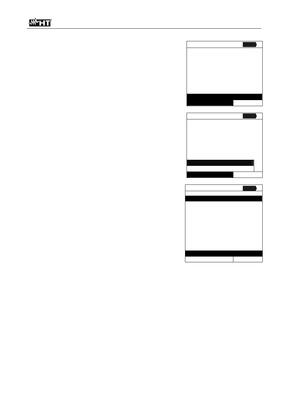
1. Position the cursor onto EFF by using the arrow keys
(
,) and confirm with ENTER. The display shows the
values of the output electrical parameters of the
photovoltaic generator.
15/05/12 15:34:26
I r r
- - -
W / m 2
P n o m
3 . 5 0 0
k W
T c
- - -
° C
T e
- - -
° C
P d c
0 . 0
k W
V d c
0 . 0 0 0
V
I d c
0 . 0
A
n d c
- - -
G O t o S t a r t
Selection
E F F
2. Press the ENTER key. The instrument shows the
following options: System parameters and Instrument
settings
3.
Use the arrow keys (
,) to select “System
Parameters” and confirm with ENTER. The instrument
shows the following screen:
15/05/12 15:34:26
I r r
- - -
W / m 2
P n o m
3 . 5 0 0
k W
T c
- - -
° C
T e
- - -
° C
P d c
0 . 0
k W
V d c
0 . 0 0 0
V
I d c
0 . 0
A
n d c
- - -
System parameters
I n s t r u m e n t s e t t i n g s
Selection
E F F
4. By using the arrow keys (
, ) it is possible to set:
Pmax maximum total rated power of PV installation
expressed in kW
Range coefficient of power variation with
temperature, characteristic parameter of PV modules
(range: -1.00
-0.01%/C)
NOCT rated operating temperature of the cell,
characteristic parameter of PV modules (typically in
the following range: 42
48°C)
Te, Tc setting of default values of environmental
and (Te) and PV module (Tc) temperatures. These
values are taken into consideration by the instrument
only when no auxiliary probe is connected to the
remote unit SOLAR-02 (range: Te = 0°C
80°C; Tc =
0°C
100°C)
nDC Lim minimum limit of DC efficiency (default
value: 0.85 , range: 0.01
1.15)
Corr. Type Setting of the compensation
relationship on the calculation of Pdc power and the
maximization of DC efficiency (see § 5.2.3).
15/05/12 15:34:26
P m a x :
: 3 . 5 0 0 k W
G a m m a
:
- 0 . 4 5
% / ° C
N O C T
: 4 5 ° C
T e
:
4 0 ° C
T c
:
4 5 ° C
n D C L i m :
: 0 . 8 5
C o r r . T y p e . :
T . E n v .
S A V E t o S t o r e
E F F