Caution, Pvcheck – HT instruments PVCHECK User Manual
Page 35
PVCHECK
EN - 33
6.3.3. Carrying out an IVCK quick test and measuring irradiance
CAUTION
The maximum voltage between inputs P, N, E and C is 1000VDC. Do not
measure voltages exceeding the limits given in this manual.
Do not perform test on PV modules or strings connected to the DC/AC
converter
The maximum current which can be measured by the instrument is 10A.
Before carrying out the measures of IVCK and Insulation in "STRING"
mode, always ensure that the instrument is connected to ONE STRING
and not more strings in parallel to avoid possible damage of it
1. Switch on the instrument by pressing the ON/OFF key.
2. Irradiance measurement is carried out in one of the following modes:
Measurement by reference cell directly connected to PVCHECK
Measurement by reference cell connected to a connected SOLAR-02 unit RF with
PVCHECK
3. Check that the settings of remote unit SOLAR-02 are consistent with the type of
measurement to be carried out (see § 5.1.4).
4. Check the minimum irradiance value set (see § 5.1.5).
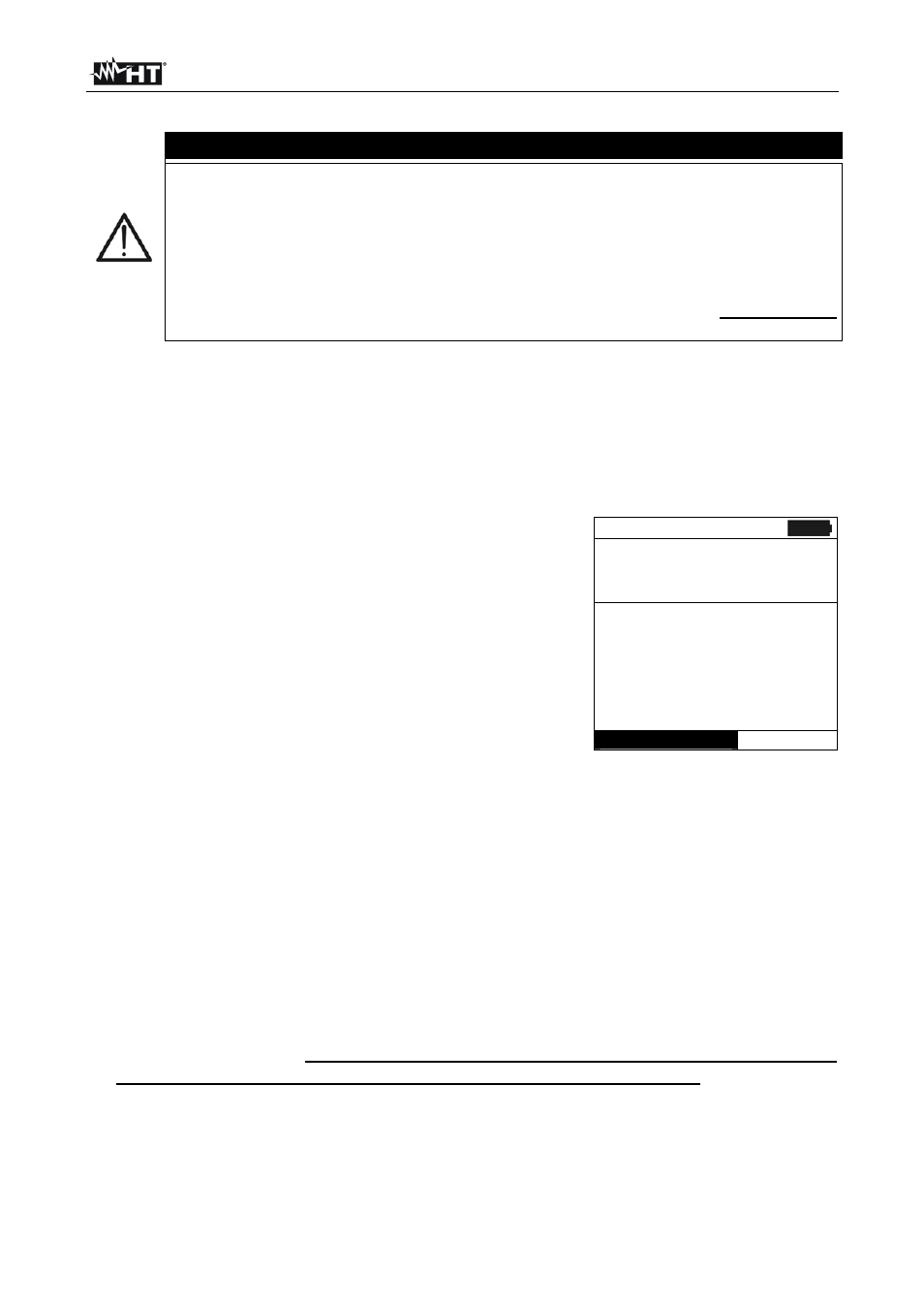
5. Position the cursor onto IVCK by using the arrow keys
(
,) and confirm with ENTER. The display shows the
screen to the side: The meaning of the parameters is the
following:
Module type of module being tested
Vdc value of output voltage from module/string
measured in real time
Irr value of irradiation measured in real time
Tc value of module temperature (see § 5.5.1)
Voc, Isc section with display of result OK/NO of
Voc and Isc measurement
Ri() the value in brackets may be NO/selected test
voltage (see § 5.5.1). The value of Ri indicates the
insulation resistance
Rpe() the value in brackets may be NO, Cal or
NoCal (see § 5.5.1). The value of Rpe indicates the
result of the continuity test.
15/05/12 15:34:26
M o d u l e :
S U N P W R 3 1 8
V d c
:
0 . 0 V
I r r
:
0 W / m 2
T c :
A u t o
° C
V o c , I s c :
R i ( 1 0 0 0 V )
- - -
M
R p e ( C a l )
- - -
Selection
I V C K
6. Press the ENTER key, select “Settings” and confirm again with ENTER. Set the
instrument as indicated in § 5.5.1
7. If necessary, press the ENTER key, select “Average Reset” and confirm again with
ENTER. Carry out this operation as indicated in § 6.3.4
8. If necessary, press the ENTER key, select “Cable calibration” and confirm again with
ENTER. Carry out this operation as indicated in § 6.5.2
9. Mount the rod onto the disc of the optional accessory M304 and keep it in touch with
the module’s surface. Make sure that the shadow cast by the rod onto the disc
falls within the “limit internal circle” on the disc itself (see Fig. 7). If this is not the
case, the incidence angle between the sun rays and the module surface is too high and,
therefore, the measurements carried out by the instrument CANNOT be considered
reliable. Repeat the same operations at another daytime.
10. Fasten the bracket to the module by using the supplied set of screws and mount the
reference cell on it, if possible with output terminals facing downwards. Rotate the