Measurements – HT instruments FULLTEST3 User Manual
Page 14
FULLTEST
3
EN - 13
5. MEASUREMENTS
5.1. CONTINUITY - TWO WIRE METHOD (RPE-2WIRE)
Complying with EN 60204-1, continuity of protective bonding circuit between PE terminal and
relevant points of the protective conductor system must be checked by injecting a measurement
current of 0.2 A up to 10 A approx.
5.1.1. RPE-2WIRE DISPLAY EXPLANATION
Adjustable/selectable parameters:
Im
NOM
- nominal measurement current
200 mA or 25 A AC
LIMIT (meas. current 200 mA) - continuity limit value 0.01
19.99, 20.0 200.0
LIMIT (meas
.
current 25 A) - continuity limit mode
STANDARD, 60204 SET Z or 60204 SET L
LIMIT (test current 25 A, STANDARD mode) -
continuity limit value
0.01
20.00
MODE - measurement mode
MANUAL or TIMER
CAL (meas. current 200 mA) - calibration of test leads 0.00
5.00
CAL (meas
.
current 25 A) - calibration of test leads 0.000
1.999, 2.00 5.00
TIMER - measurement time
00:01
60:00 (1 s 60 min), resolution 1 s
LENGTH - wire length
0.1
999.9 m, resolution 0.1 m
SECTION - wire section
1, 1.5, 2.5, 4, 6, 10, 16, 25, 35, 50 or 70 mm
2
MATERIAL - wire material
Cu (Cupper) or Al (Aluminium)
Z
LINE
- input line impedance
0.001
2.000 , resolution 0.001
PROTECTION - over-current protection device
MCB B, MCB C, MCB D, MCB K, FUSE gG or
FUSE
aM
In - nominal current of protection device
Depends on selected protection device, see the
chapter 5.1.3. LIMIT VALUE ADJUSTMENT
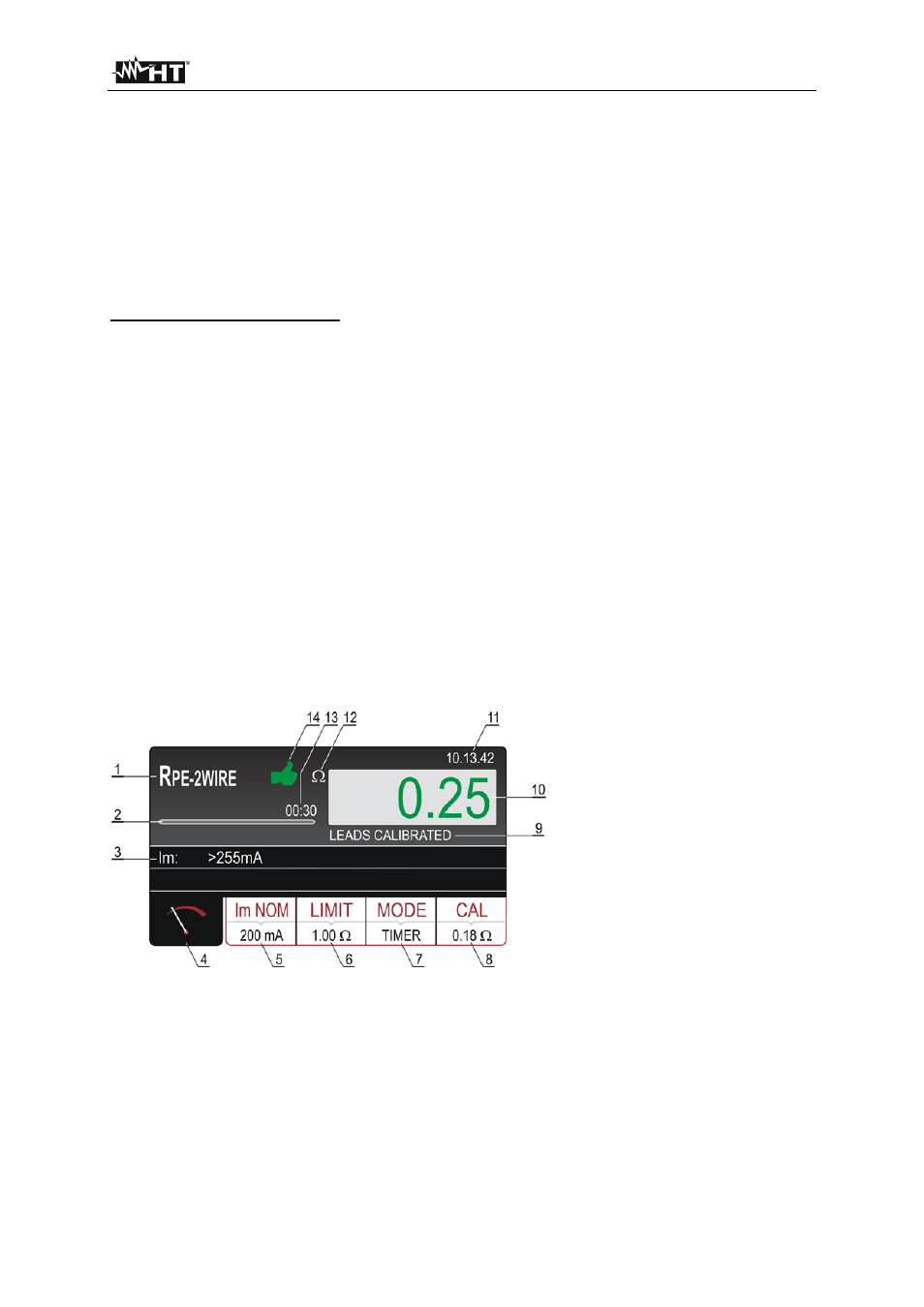
Figure 5
: Display with R
PE-2WIRE
test result
1 ..... Selected function.
2 ..... Progress bar, it follows measurement time during the measurement (in TIMER mode only).
3 ..... Sub-result - measurement current Im that was flowing through UUT during the measurement.
4 ..... Measurement screen touch-screen key.
5 ..... Im NOM touch-screen key to select nominal test current (200 mA or 25 A). Currently selected value
is displayed on the bottom of the key.