The system diagram and description – GW Instek PST-Series User Manual User Manual
Page 17
PST-3201/3202 PROGRAMMABLE POWER SUPPLY
USER MANUAL
⎯ 28 ⎯
[Step 8]
Set the cursor to [Save] by using the knob and press [ENTER] to
terminate the calibration with storing. If want to cancel the calibration,
using the knob to set the cursor to [EXIT] and press [ENTER] to
terminate the procedure without storing.
6-4. Cleaning
To clean the power supply, use a soft cloth dampened in a solution
of mild detergent and water. Do not spray cleaner directly onto the
instrument, since it may leak into the cabinet and cause damage. Do
not use chemicals containing benzine, benzene, toluene, xylene,
acetone, or similar solvents. Do not use abrasive cleaners on any
portion of the instrument.
PST-3201/3202 PROGRAMMABLE POWER SUPPLY
USER MANUAL
⎯ 29 ⎯
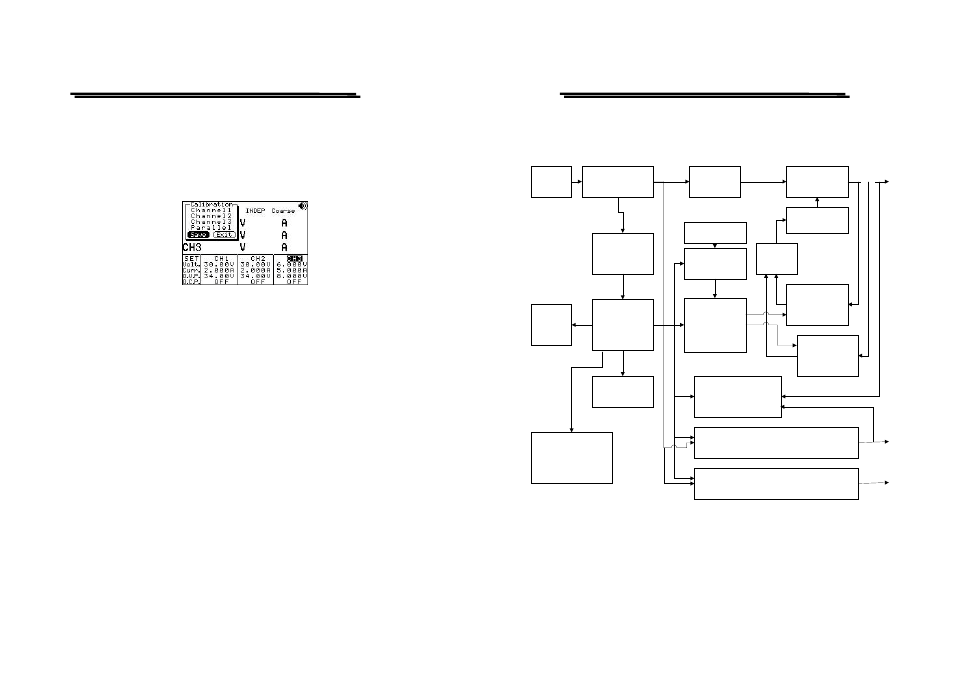
7. THE SYSTEM DIAGRAM AND DESCRIPTION
7-1. Block Diagram
The graph above is the system diagram of PST-SERIES, Which consists
of Micro Processor Unit (MPU), Digital to Analog Converter (DAC),
Analog Switch Circuit, Reference Voltage Circuit, Driver Circuit,
Control Circuit, Track/Parallel Circuit, Comparator, and etc.
AC
INPUT
TRANSFORMER
RELAY
CONTROL
VOLTAGE
COMPARATOR
CURRENT
COMPARATOR
D TO A
CONVERTER
REFERENCE
ANALOG
SWITCH
AND SAMPLE
HOLD
MICRO
CONTROL
LCM
DISPLAY
KEYBOARD
TRACK AND
PARALLEL CONTROL
CH2
CH3
AUX
RECTIFIER
AND FILTER
SERIES
REGULATOR
AMPLIFIER
OR
GATE
O/P
INTERFACE
RS-232 OR GPIB