Fire-Lite MS-2410BC Conventional Control Panel User Manual
Page 35
Document #50801 Rev. C 12/14/01 P/N 50801:C
35
Programming Function
is on steady, acts as a 'pointer', indicating the control panel feature that will be programmed. The blinking zone trou-
ble LED acts as a 'cursor', indicating the option for the currently selected program feature. The Up and Down arrow
keys can be used to position the 'cursor' at any Zone trouble LED.
3.4.1 Program Feature Selection
Position the 'pointer' at the zone alarm LED, corresponding to the program feature that is to be changed, by pressing
the Enter key. Refer to Table 3-2, “Program Feature Indicated by Alarm Zone,” on page 39, for a listing of all pro-
gram features and their corresponding alarm zones. Repeated presses of the Enter key will move the 'pointer' through
all 10 zone alarm LEDs without changing any options.
As the 'pointer' is positioned at each zone alarm LED, the Zone 1 trouble LED will blink and additional zone trouble
LEDs may light steady, indicating the options selected for that program feature.
3.4.2 Programming Options
The zone trouble LEDs are used to indicate the programming options for each feature. The 'cursor' (blinking LED)
will be positioned initially at the Zone 1 trouble LED. Note that additional zone trouble LEDs may be on steady if the
corresponding option has been previously programmed for the current feature. Use the Up and Down arrow keys to
position the 'cursor' at the zone trouble LED corresponding to the option which is to be programmed. Press the key-
pad 3 key (Disable/Enable) to toggle between selecting and deselecting the option. Following option selection for the
current control panel feature, press the Enter key to store the selection and move the 'pointer' to the next feature (zone
alarm LED). Enabling or selecting an option will cause the corresponding zone trouble LED to turn on steady when
the 'cursor' is moved off the LED.
Note that the normal blink rate of the 'cursor' (blinking LED), when positioned on an option that is disabled or not
selected, is mostly off (1/10 second On and 9/10 second Off). If the 'cursor' is positioned on an option that is selected
or enabled, the blink rate will be mostly on (9/10 seconds On and 1/10 second Off).
3.4.3 Programming Example
In this example, the Supervisory Alarms will be programmed so that both Zones 9 and 10 are auto-resettable
supervisory circuits. Refer to Table 3-2, “Program Feature Indicated by Alarm Zone,” on page 39, to see that the
Supervisory Alarms feature corresponds to Zone 4 alarm LED.
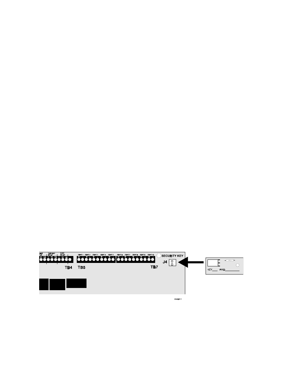
1.
Insert the Security Key into connector J4 on the MS-2410BC main circuit board
Security Key
P/N: PKB
MS-2410BC