Edwards Signaling 2447T Integrity Temporal Horn User Manual
Page 2
2 / 4
P/N P-047550-1779 • REV 7.0 • ISS 06MAY11
Mounting the electrical box
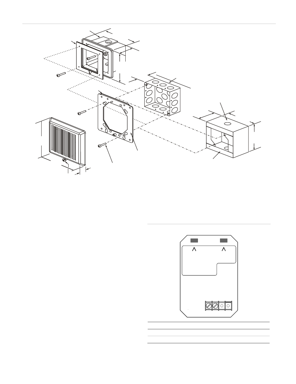
Figure 2 shows mounting details for:
•
Standard box. When using a 4 in. square box, use an
extension ring for additional wiring space, if needed. If
using a double-gang electrical box that is 2-1/2 in.
(64 mm) deep, locate the conduit only at the rear of the
box.
•
Weatherproof box. Peel off the adhesive backing from the
gasket and adhere to the box.
•
Surface mount box.
Selecting the volume and pattern
The horn has a jumper for selecting a high or low volume
output level. The default is high volume. To set the output to
low volume, remove the output jumper from the circuit board
on the rear of the unit. See Figure 3.
The horn has a jumper for selecting either a temporal or steady
tone. The default is temporal tone. To set the output to steady
tone, remove the tone jumper from the circuit board on the rear
of the unit. See Figure 3.
Tip:
Save the jumper by sliding it onto a single pin.
Figure 3: Jumper setup and terminal block
REMOVE FOR
LOW OUTPUT
REMOVE FOR
CONT. TONE
HORN
+
HORN
–
STROBE +
STROBE –
1
2
3
4
( )
1
( )
2
Item In
Out
(1)
High output
Low output
(2)
Temporal tone
Continuous tone
Figure 2: Mounting diagram
5-59/64 in.
(150 mm)
3-13/32 in.
(87 mm)
5-59/64 in.
(150 mm)
5/8 in.
(16 mm)
2-1/8 in.
(54 mm)
5-1/2 in.
(140 mm)
5-1/2 in.
(140 mm)
5-5/8 in.
(143 mm)
5-5/8 in.
(143 mm)
3-5/16 in
(84 mm)
(1)
(3)
(4)
(5)
(2)
(6)
( )
7
(8)
(9)
.
(1) Gasket with adhesive backing
(2) Weatherproof
box
(3) Standard
box
(4) Knockouts for 1/2 in. (13 mm) or 3/4 in. (19 mm) conduit top,
bottom, back
(5) Surface mount box
(6) Mounting plate (supplied with horn)
(7) #8-32
screw
(8) Captive locking screw
(9) Hook
flange