Edwards Signaling 2447T Integrity Temporal Horn User Manual
Integrity temporal horn installation sheet, Description, Installation
© 2011 UTC Fire & Security. All rights reserved.
1 / 4
P/N P-047550-1779 • REV 7.0 • ISS 06MAY11
Description
The Integrity Temporal Horn is a fire alarm notification
appliance designed for indoor or outdoor walls and ceilings.
See Table 1 for temporal horn model numbers and Table 2 for
accessory model numbers.
Table 1: Models
Description Numbers
Temporal horn, red
757-1A-T
XLS757-1A-T
INT-T
2447TH-R
Temporal horn, white
757-1A-TW
XLS757-1A-TW
INT-TW
2447TH-W
Table 2: Accessories
Description Numbers
Surface box, red, indoor
757A-SB
XLS757A-SB
INT-SB
2459-SMB-R
Surface box, white, indoor
757A-SBW
XLS757A-SBW
INT-SBW
2459-SMB-W
Weatherproof box, red,
outdoor
757A-WB
XLS757A-WB
INT-WB
2459-WPB-R
Weatherproof box, white,
outdoor
757A-WBW
XLS757A-WBW
INT-WBW
2459-WPB-W
Bi-directional mounting
frame, red, indoor
757A-BDF
XLS757A-BDF
INT-BDF
Bi-directional mounting
frame, white, indoor
757A-BDFW
XLS757A-BDFW
INT-BDFW
Installation
WARNING:
Electrocution hazard. To avoid personal injury or
death from electrocution, remove all sources of power and
allow stored energy to discharge before installing or removing
equipment.
Note:
Electrical supervision requires the wire run to be broken
at each terminal. Do not loop the signaling circuit field wires
around the terminals.
Install this product in accordance with applicable requirements
in the latest editions of NFPA 72 National Fire Alarm and
Signaling Code, CSA C22.1 the Canadian Electrical Code, Part
1, Section 32, CAN/ULC-S524 Installation of Fire Alarm
Systems, and in accordance with the local authority having
jurisdiction.
To install the temporal horn:
1. Select and install a suitable electrical box. See “Mounting
the electrical box” on page 2 for details.
Note: Outdoor installations require a weatherproof
backbox.
2. Set the tone and pattern. See “Selecting the volume and
pattern” on page 2 for details.
3. Bring the signal circuit field wiring into the electrical box.
4. Position the mounting plate on the electrical box with the
hook flange up and facing outward as shown in Figure 2.
Fasten the plate using the screws provided.
5. Connect the signal circuit field wiring. For the unit to
function properly, observe polarity. See Figure 1.
For additional wiring details, see the installation
instructions for the signaling modules or circuits used in
the fire alarm control panel.
6. After completing the connections, attach the unit to the
mounting plate, as noted below.
a. The grille has tabs (at the top of the inner face) that
engage with the hook flange on the mounting plate.
Angle the bottom of the grille out slightly, and then
slide the unit into place so that the tabs engage the
flange.
b. Seat the grille by pressing the bottom in.
c. Fasten the bottom of the grille to the mounting plate
by tightening the captive locking screw.
7. Apply power and activate the unit to verify that it is
operating properly.
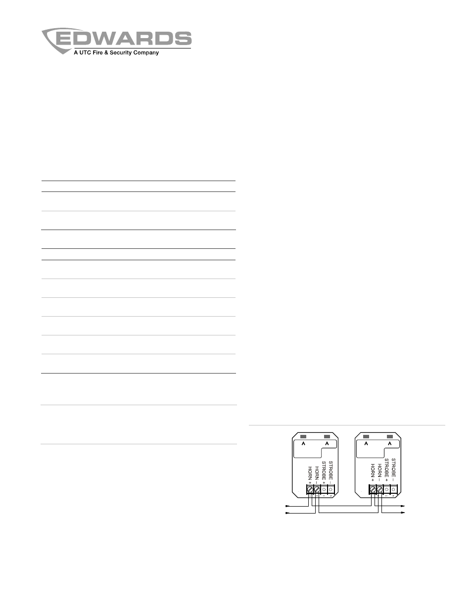
Figure 1: Typical wiring diagram
( )
1
(2)
NAC +
NAC +
NAC –
NAC –
Polarity is shown in the active state.
(1) From UL/ULC Listed fire alarm control panel signal circuit.
(2) To next device or end of line resistor for Class B. Return to control
panel for Class A connection.
Integrity Temporal Horn Installation Sheet