Category 4 wiring diagram, Guardswitches – Edwards Signaling INT-03 Series User Manual
Page 3
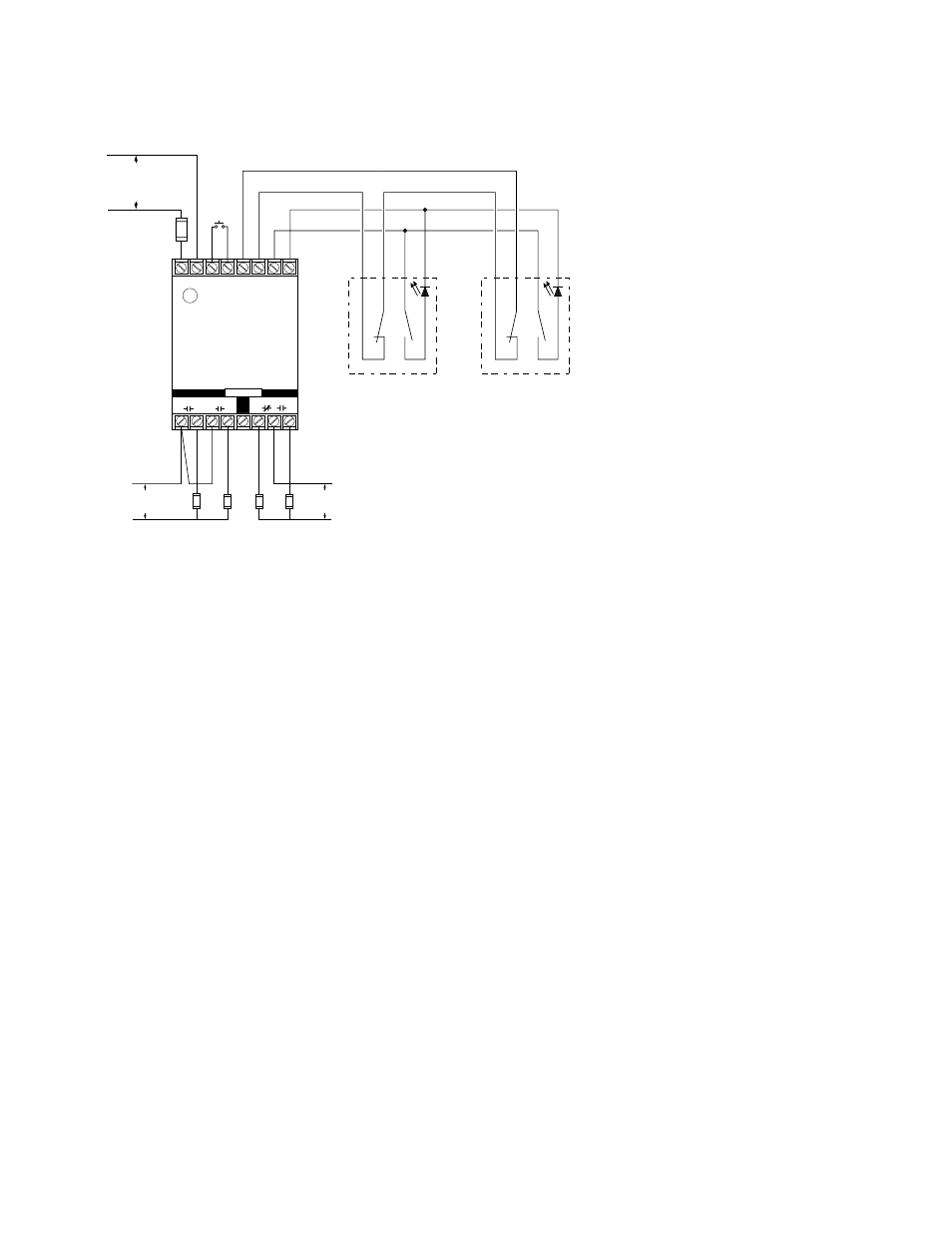
Category 4 Wiring Diagram
GuardSwitches
™
are shown with the actuators in position—guard is closed. Inputs are shown with safety/guard in closed position. Two 300-B Series Guardswitch
™
and one INT
relay are required for each safety gate.
*300-BLT-
*Or other DPST GuardSwitch
(See the 300-BT Series
installation instructions)
( – )
( + )
INT-03-230: 230V AC
INT-03-120: 120V AC
INT-03-024: 24V DC
R e q u i r e d F a s t o r
S l o w - A c t i n g F u s e :
( 2 5 0 V , 5 x 2 0 m m F )
I N T - 0 3 - 2 3 0 : 4 0 m A
I N T - 0 3 - 1 2 0 : 8 0 m A
I N T - 0 3 - 0 2 4 : 1 / 4 A
Required Fast or
Slow-Acting
Fuses: 4A (250V,
5x20 mm F
W
H
T
B
L
K
R
E
D
B
L
U
*300-BLT-
W
H
T
B
L
K
R
E
D
B
L
U
Note – The LED on the BLT model
will be ON when the guard is open
Fuses: 1A (250V)
RESET
A
SAFE
AUX.
B
C
D
E
F
G
OUTPUTS
230 VAC
60 VDC
120 VAC
30 VDC
LOADS
–
+
L1
L2
1
2
X1 X2
Y1
Y2
N.O.
N.C.
Safety Monitor Relay
INT-03
Note: Only outputs AB and CD are safety outputs. Auxiliary form C output E, F, G may fail in an unsafe condition and should only be used for signaling.
- 888D-N5 (4 pages)
- 888D-N5 (3 pages)
- 439D Series (3 pages)
- 101XBRM Series (5 pages)
- 104 GuardSwitch (2 pages)
- 105XBRi Series (5 pages)
- 250-CO (8 pages)
- 111 GuardSwitch (2 pages)
- 113 GuardSwitch (3 pages)
- 124 GuardSwitch (2 pages)
- 125 Class Halogen (4 pages)
- 125 Class Incand (2 pages)
- 125 Class Standard LED (2 pages)
- 125XBR LED (4 pages)
- 125XBRi Chameleon (4 pages)
- 126 GuardSwitch (2 pages)
- 128C GuardSwitch (2 pages)
- 215-F6 GuardSwitch (4 pages)
- 2302 SERIES (2 pages)
- 2315 Series (2 pages)
- 2400 Series (79 pages)
- 251-F6 (4 pages)
- 291-F6 (4 pages)
- 291-F7 (4 pages)
- 300 Series (4 pages)
- 300 Series (1 page)
- 301 (2 pages)
- 302 (2 pages)
- 5530M (8 pages)
- Genesis Signal Master Module (2 pages)
- ADTG4RB (2 pages)
- Genesis Speaker Strobe (4 pages)
- Genesis Remote Mount Signal Master Module (4 pages)
- EBPS Remote Booster Power Supply (64 pages)
- Genesis Temporal Horn (4 pages)
- Genesis Strobe (2 pages)
- Genesis Temporal Horn-Strobe (4 pages)
- Genesis Chime (2 pages)
- Genesis Chime-Strobe (4 pages)
- Genesis Ceiling Speaker (2 pages)
- Genesis Ceiling Strobe (2 pages)
- Genesis High Candela Ceiling Strobe (4 pages)
- Genesis Ceiling Speaker-Strobe (4 pages)
- Genesis High Candela Ceiling Speaker-Strobe (4 pages)
- Genesis Ceiling Horn-Strobe (4 pages)