Caution, Warning, Maintenance – Edwards Signaling 106DEXST-FJ User Manual
Page 2
P/N 3100101 ISSUE 6
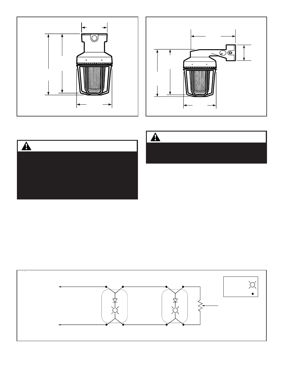
Figure 2. Detail of Ceiling Mounting
Figure 3. Detail of Bracket Mounting
Figure 4. Wiring Diagram
NOTE: DC polarity of circuit shown in supervisory state (signal inactive). Circuit polarity to reverse to activate signal.
Electrical supervision requires wire run to be broken at each device.
Device for constant input voltage. Do not connect to “coded” or pulsating voltage.
From Power Source
or
Previous Signaling Device
End-of-Line Resistor,
when required with
supervised system
KEY:
Light symbol -
Wire nut symbol -
(+)
Red
(+)
Red
(+)
Red
(+)
Red
Black
(-)
Black
(-)
Black
(-)
Black
(-)
Series
106DEX
Series
106DEX
(+)
(-)
NOTE:
For non-fire alarm use without field wire supervision installer can tie the two red leads together and
tie the two black leads together.
For strobe tube replacement, disconnect from the supply
circuit and allow five (5) minutes for stored energy to dis-
sipate before starting work or disassembly (Figure 6).
1. Loosen the (3) guard screws and remove the guard.
2. Loosen the globe and ring assembly set screw. Insert
a suitable tool into the notches in the globe and ring
assembly and loosen the assembly by prying in a
counterclockwise direction. Remove the ring and
globe assembly.
Maintenance
Maintenance
Maintenance
Maintenance
Maintenance
CAUTION
When replacing the strobe tube, do not handle the
tube. Hold the strobe tube only by its base to pre-
vent damage to the tube.
3. Refer to Table 2 for the correct replacement catalog
number and replace the necessary part.
4. To replace, simply screw the unit on until it seats firmly
onto its gasket. Tighten the unit another 1/8 to 1/4
turn. Tighten the setscrew.
5. Reinstall the guard, where applicable, and secure using
the three supplied screws.
6. After the unit is assembled, apply power and make
sure the unit functions properly.
WARNING
To reduce the risk of ignition of hazardous atmo-
spheres and shock, keep assembly tightly closed
when circuits are energized.
To reduce the risk of ignition of hazardous atmo-
spheres and shock, disconnect from the supply and
circuit and allow five (5) minutes for stored energy to
dissipate before disassembling the unit.
13.88"
(352.6 mm)
12.38"
(314.45mm)
13.75"
(349.25mm)
7.80"
(198.12mm)
4.93"
(125.2mm)
5.95"
(151.13mm)
13.0"
(330.2mm)
13.38"
(339.85mm)
7.80"
(198.12mm)