Edwards Signaling Genesis WG4 Speaker User Manual
Genesis wg4 speaker installation sheet, Description, Installation
© 2011 UTC Fire & Security. All rights reserved.
1 / 4
P/N 3101852 • REV 2.0 • ISS 21MAR11
Genesis WG4 Speaker Installation Sheet
Description
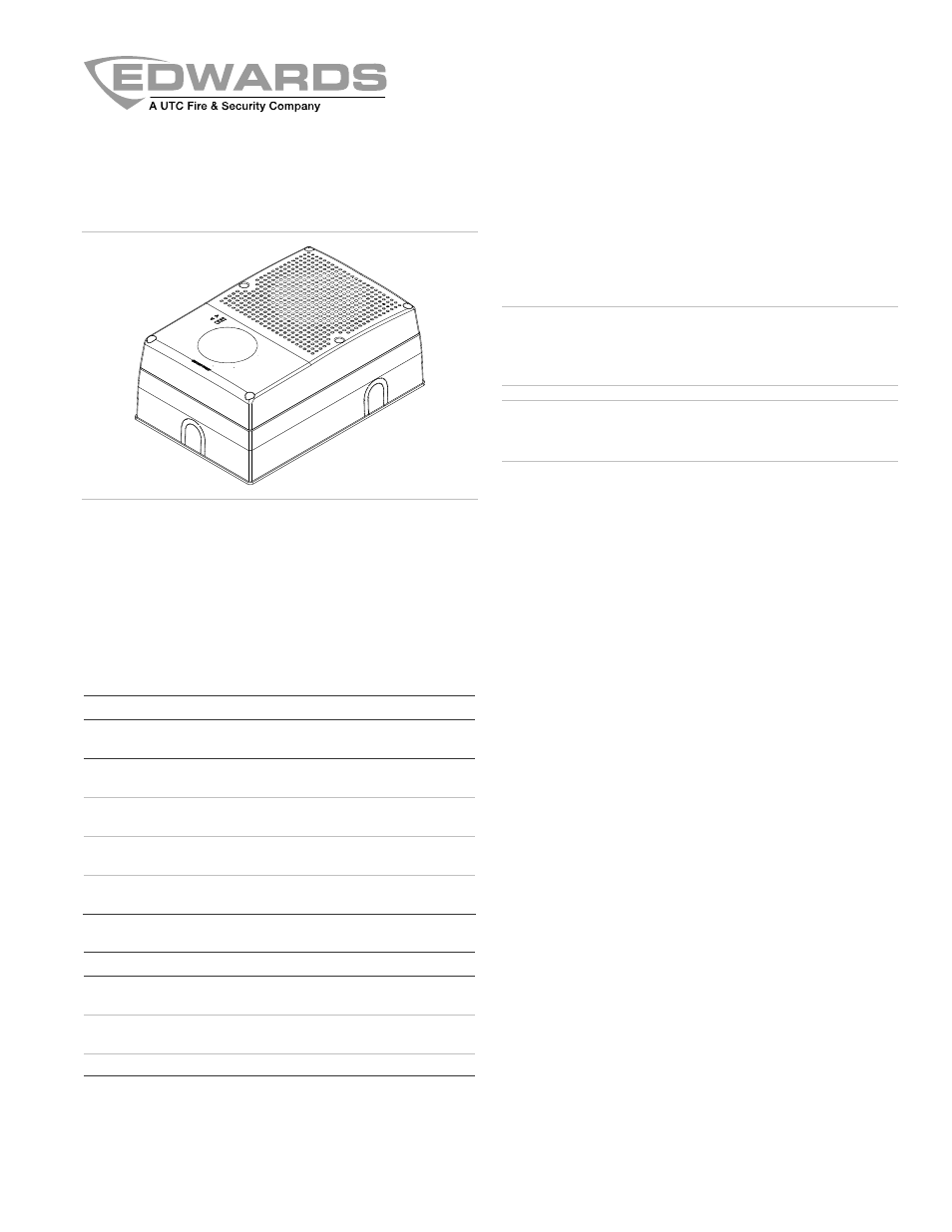
The Genesis WG4 Speaker is a fire alarm and mass
notification and emergency communication (MNEC) appliance
designed for indoor or outdoor wet location use on ceilings or
walls. See Table 1 for a list of models and Table 2 for a list of
accessories.
Table 1: Models
Number Description
WG4WA-S Outdoor-rated
wall/ceiling speaker (25/70 V), multi-
tap, white with ALERT marking
WG4WN-S Outdoor-rated
wall/ceiling speaker (25/70 V), multi-
tap, white
WG4RN-S
Outdoor-rated wall/ceiling speaker (25/70 V), multi-
tap, red
WG4WF-S Outdoor-rated
wall/ceiling speaker (25/70 V), multi-
tap, white with FIRE marking
WG4RF-S
Outdoor-rated wall/ceiling speaker (25/70 V), multi-
tap, red with FIRE marking
Table 2: Accessories
Number Description
WG4WTS [1]
Outdoor-rated surface skirt, white - for Genesis WG4
speaker or speaker/strobe
WG4RTS [1]
Outdoor-rated surface skirt, red - for Genesis WG4
speaker or speaker/strobe
WGRGSKT
Appliance replacement gasket
[1] The trim skirt is outdoor-rated when used with the 449 weatherproof
box.
Installation
Install this device in accordance with the latest edition of NFPA
72 and the local authority having jurisdiction.
WARNING:
Electrocution hazard. To avoid personal injury or
death from electrocution, remove all sources of power and
allow stored energy to discharge before installing or removing
equipment
Caution:
Electrical supervision requires the wire run to be
broken at each terminal. Do not loop the signaling circuit field
wires around the terminals.
Note:
The Genesis WG4 Speaker may be ceiling-mounted or
wall-mounted and may be placed in one of four positions. See
Figure 4. Place the electrical box accordingly.
To install the speaker:
1. Remove the cover from the speaker by first removing the
six cover screws. See Figure 1.
2. If desired, place the optional trim skirt over the electrical
box. See “Specifications” for a list of compatible boxes.
3. Remove the gasket that comes with the 449 weatherproof
box and replace it with the gasket that comes with the
WG4 speaker.
4. Place the gasket over the backplate, and then feed the
field wiring through the wire slots on the gasket and the
backplate. See Figure 2, item 2.
5. Secure the backplate to the electrical box with four
screws.
6. Connect the wiring to the terminal strip.
7. Connect the speaker to the audio NAC. Observe polarity.
See Figure 2.
8. Set the speaker voltage.
The default speaker voltage is 70 V. For 25 V, reposition
the speaker voltage selection switch S3. See Figure 2,
item 3.
9. Set
the
wattage.
The wattage default setting is Z corresponding to 1/4 watt.
To select a different wattage, align the S1 indicator to the
desired wattage setting. See Table 3 and Figure 2, item 1.
10. Position the cover over the backplate, and then secure it
with the six cover screws.
11. Test the unit for proper operation.