Detcon 1600A-N4X User Manual
Page 15
1600A-N4X
1600A-N4X Instruction Manual
Rev. 0.2
Page 11 of 38
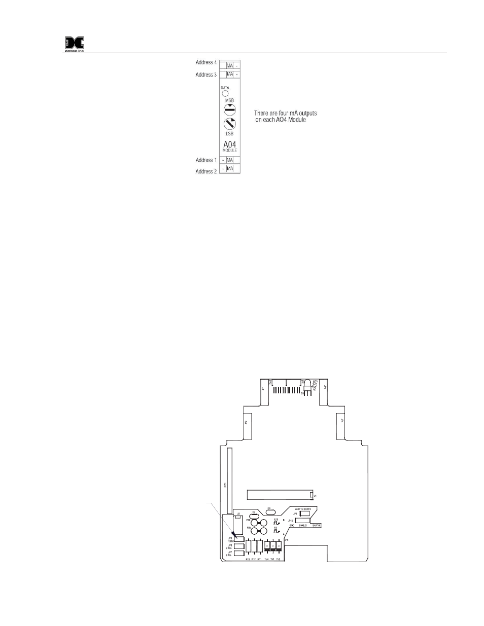
Figure 14 Model AO-4 Module
General Wiring Notes:
When I/O Modules are located at a remote distance from the controller, an end-of-line terminating resistor
is required to enhance communications reliability. Identify the last I/O Module in the loop, and open the
module casing using the clip release points. Locate and install the jumper on JP6 (TERM) Figure 15. This
adds a 120
: resistor to the end of the line. If applicable, add a 120: resistor to the last Modbus™ gas
sensor.
Follow generally accepted guidelines for RS-485 serial networks. Do not wire I/O Modules and/or
Modbus™ gas sensors in long-distance ‘T-Tap’ configurations. Stay with direct serial configurations. See
Appendix A for serial communications configuration guidelines.
Use Detcon Recommended cabling whenever possible.
x Belden P/N 1502P cable is recommended for a single cable providing serial communications and
power.
x Belden 9841 cable is recommended for a single cable providing serial communications only.
Ground the cable shielding at the Model 1600A-N4X Controller only. Other points of grounding may
cause a ground loop, and induce unwanted noise on the RS-485 line, which in turn may disrupt
communications.
Jumper located
on component
side of PCB
Figure 15 Location of Termination jumper (JP6)