3 installing i/o modules, 4 connecting to the i/o modules, Figure 9 i/o module installation – Detcon 1600A-N4X User Manual
Page 12
1600A-N4X
1600A-N4X Instruction Manual
Rev. 0.2
Page 8 of 38
closed switch to these terminal blocks. If more than one switch is to be connected, the switches must be
connected in series.
NOTE: The Remote Alarm Reset switch should be a ‘Normally Closed’ Switch and should be wired as
such. Failure to wire the switch correctly will cause the Enclosure Alarm Reset and all subsequently
connected Remote Alarm Reset Switches to be non operational.
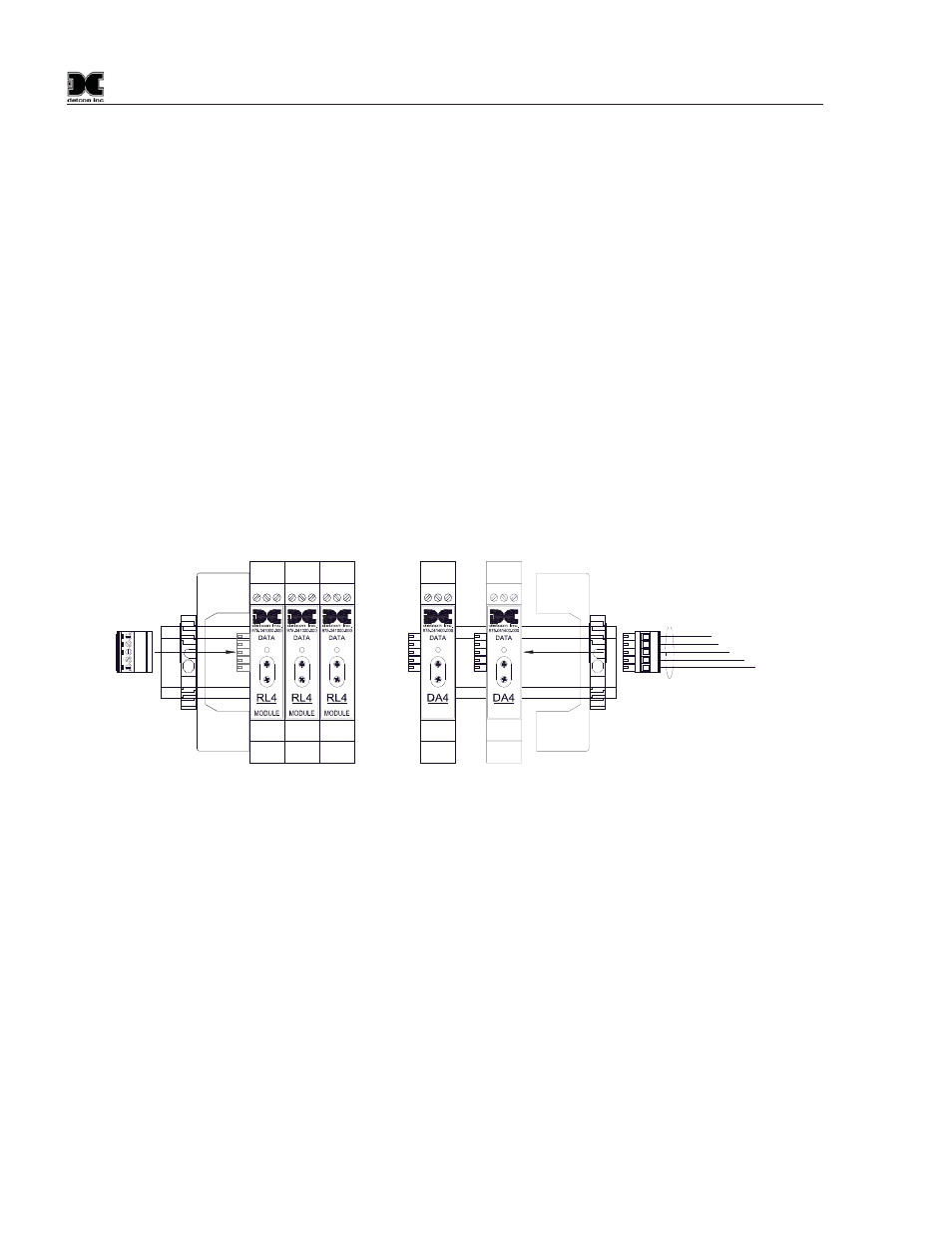
3.3 Installing I/O Modules
A maximum of 12 I/O modules may be installed in the 1600A NEMA 4 enclosure. Additional modules should
be mounted in a separate enclosure.
I/O modules are mounted on industry-standard 37.5 x 7.5 mm din-rail. Install the first I/O module on the left
side of the din-rail. Plug the Female Connector (TB2-J1) from the RS-485 Output Terminal Blocks onto the
Left Most Module. Slide it all the way to the left side stop. Add additional modules to the right. When
installing additional I/O modules, make sure there is about 0.5 inch clearance on either side of the module and
snap the module onto the din rail (the 0.5” spacing is to allow for connector clearance). Once the I/O module
is snapped onto the din-rail, slide it to the left and assure that it firmly plugs into the next module. The unit
will accommodate up to 12 I/O Modules. Additional modules should be mounted in a separate enclosure.
Connect the RS-485 and Power Connector to the last module installed on the right side of the Din Rail. Secure
End-Stop.
4-20mA
INPUT
COMM
M
S
D
L
S
D
RELAY
COMM
M
S
D
L
S
D
RELAY
COMM
M
S
D
L
S
D
RELAY
COMM
M
S
D
L
S
D
SB
A
-
+
S
B
A
-
+
4-20mA
INPUT
COMM
M
S
D
L
S
D
RS-485 and Power Cable
RS-485
Cable to
Output Terminal
Blocks.
Add
Additional
Modules
as
needed.
Maximum
of 12
Modules.
TB2-J1
TB2-J2
Figure 9 I/O Module Installation
NOTE: The TB2-J1 Connector must be plugged into to the I/O Module on the left hand side of the Din
Rail. If this connector is not properly installed, communication with other RS-485 devices will not be
possible. Refer to Secondary Modbus™ Port Section 5.5
NOTE: If no I/O Modules are installed in the unit TB1-J1 and TB1-J2 must be plugged into each other
for the RS-485 to communicate.
For addressable I/O modules or Modbus™ sensors that are being located remotely from the Model 1600A-
N4X controller use Belden 1502P cable for serial and power connections. For serial only connections use
Belden 9841 cable.
3.4 Connecting to the I/O Modules
4-20mA Gas Sensors
Connect 4-20mA type gas sensors to the Model DA4 4-20mA input modules. There are four 4-20mA inputs
in each Model DA4 module.