2 remote alarm reset switch – Detcon 1600A-N4X User Manual
Page 11
1600A-N4X
1600A-N4X Instruction Manual
Rev. 0.2
Page 7 of 38
J1
J3
J4
J5
U1
U2
1
2
3
4
5
6
7
8
9
10
+
-
NC
NO
C
+
-
A
B
SHLD
Shld
B
A
11
12
XPSN
PWR
XPSN
GND
SCRN
PWR
SCRN
GND
PLC
PWR
PLC
GND
NO
COM
FLT
RST
PO
W
E
R
IN
FA
UL
T /
N
O
CO
M
RE
SET
RS 4 8 5
FAULT
NO COMM
RST
R
G
R
G
R
G
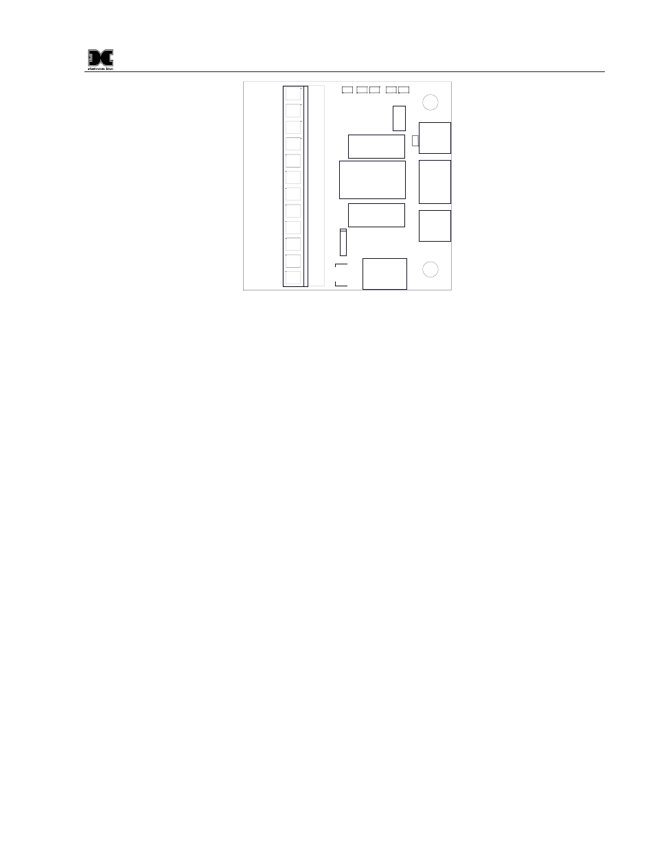
Figure 8 1600A Interface PCA
1600A Interface PCA (located on back of Display Panel)
LEDS:
RST
—This LED is normally off. It glows red when the external reset switch is pressed
FAULT
—This LED is normally red.
NO COMM
—This LED is normally green. It will glow red when a sensor or I/O module is not
communicating. A sensor fault will also cause this LED to glow red.
POWER IN
—This LED will glow green when the system is powered on.
Terminal Block Inputs:
XPSN PWR
+24VDC connection for PLC expansion module
XPSN GND
Ground connection for PLC expansion module
SCRN PWR
+24VDC connection for touch screen
SCRN GND
Ground connection for touch screen
NO COM
PLC output that is set to +24VDC when a NO COMM or senor fault condition occurs
FLT Not
used
RST
Input from external reset switch
A
Primary Modbus ‘A’ connection
B
Primary Modbus ‘B’ connection
SHLD
Primary Modbus shield connection. Not used.
3.2 Remote Alarm Reset Switch
The unit includes connections for an optional Remote Alarm Reset Switch. A set of Terminal Blocks is
supplied for the connection of a Remote Alarm Reset Switch that can be mounted anywhere outside the unit.
The Remote Alarm Reset incorporates a set of normally closed contacts that cause the unit to reset the Alarms
when contact is broken. To install a Remote Reset Switch the jumper between terminal blocks 8 and 9
(labeled “Remote Reset”) must be removed and the switch wired to these terminals. Connect only a normally