4 instrument settings, 1 settings at the instrument – LumaSense Technologies IS 50-LO plus User Manual
Page 19
IS 50-LO plus / IGA 50-LO plus Manual
Instrument Settings 19
4 Instrument settings
The pyrometers are equipped with a wide range of setting options for optimal adaption to the
required measuring condition and for getting the correct measuring temperature (description of
all available parameters see Chapter 5 Parameter description / settings).
All instrument settings can be done directly at the instrument or via serial interface and
software InfraWin.
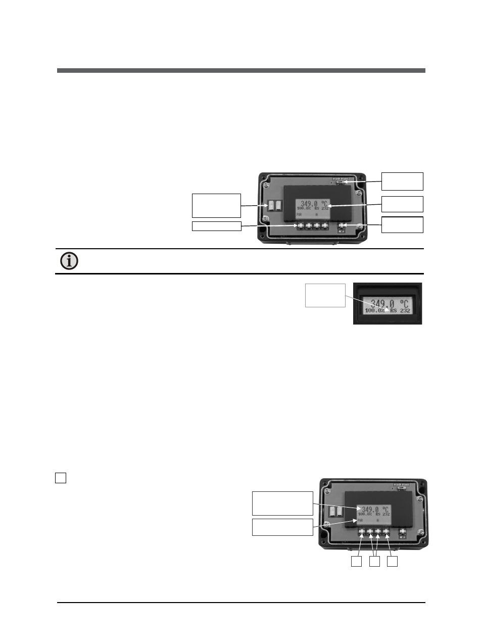
The LC-display as well as the
push buttons for displaying and
setting of the parameters are
located inside the converter. The
pyrometer is opened by 4 Allen
screws. ‘
Note: Please make sure that the pyrometer is not contaminated while open. Please
close cover right after parameterization and keep cover closed for permanent use.
With the interface switch the interface operation mode
RS232 or RS485 can be selected. The LC display shows as
chosen either RS232 or RS485.
The diagnostic push button „test“ generates a current on
the analog output which is used to check if a connected
external indicator shows the correct temperature value. The test current output is centered to
the chosen analog output span, consequently 10 mA is supplied if the analog output is adjusted
to 0 to 20 mA and 12 mA is supplied if the analog output span is set from 4 to 20 mA. The LC
display indicates the respective current along with the corresponding temperature. For example
if a measuring range of 700 °C to 1800 °C is selected the temperature shown in the display is
1250 °C). This temperature must be reflected exactly by the indicator which is supplied by the
respective current. If this is not the case the selected analog input current span of the indicator
is not equivalent to the chosen current output span of the pyrometer and one of the current
spans or temperature range have to be modified. By pressing the „test“ push button once again
or by pressing any push button of the LC-display the test current is switched off. Also after 1
minute idle time the “test” current is switched off. The unit will be in the measurement mode
again.
4.1 Settings at the instrument
1 PAR:
With
the PAR button all
available parameters are
displayed in the order they are
described in Chapter 5). Pushing
the button again changes the
display to the next parameter
and on the display a
corresponding short form is
displayed (see Chapter 5, in
brackets behind the parameter
names).
Illuminated
display
push buttons
Test current
button
contacts of the
laser targeting
light button
Interface
switch
Display of
the selected
interface
2
1
3
Push button
short description
Temperature
display or para-
meter short form