3 controls and installation, 1 electrical installation, Connector pin j – LumaSense Technologies IS 50-LO plus User Manual
Page 13
IS 50-LO plus / IGA 50-LO plus Manual
Controls and Installation 13
3 Controls and Installation
3.1 Electrical Installation
The series 50 pyrometers are powered by a voltage of 24 V DC (possible range 12 ... 30 V) or AC
(48 ... 62 Hz). Once connected to power, the instrument operates immediately and needs no
warm-up time. To switch off the instrument, unplug the connector.
To meet the electromagnetic requirements, a shielded connecting cable must be used. The
shield of the connecting cable has to be connected only on the pyrometer side to avoid ground
loops.
LumaSense offers connecting cables, but they are not part of standard scope of delivery. The
main connecting cable has wires for power supply, interface, analog output, external laser
switch and external clear of maximum value storage via contact and 12 pin angle connector (see
Chapter 10, Reference numbers). The cable includes a short RS232 adapter cable with a 9 pin
SUB-D connector for direct PC communication. This adapter is not used in combination with
RS485 interface.
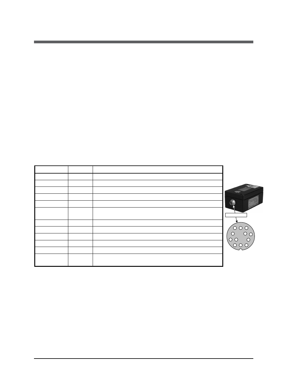
3.1.1 Pin assignment for the connector on the back of the pyrometer
Pin Color Indication
K
A
B
C
D
J
G
F
E
H
M
L
Male socket
Pin assignment
(side of male inserts)
K
white
+ 24 V power supply (or 24 V AC)
A
brown
0
V power supply
L green
+ I
outp.
analog output
B yellow
– I
outp.
analog output
H
gray
external
switch
for
targeting
light
(bridge
to
K)
J pink
see below: output for switch contact, external clearing
of maximum value storage or input for hold function
G
red
DGND
(Ground
for
interface)
F
black
RxD
(RS232)
or
B1
(RS485)
C
violet
TxD
(RS232)
or
A1
(RS485)
D gray/pink B2 (RS485) (bridge to F)
E
red/blue A2
(RS485)
(bridge
to
C)
M orange
Screen only for cable extension, don’t connect at the
switchboard
Connector pin J
The connector pin J can be used for 3 different functions:
1) Switch contact: The pyrometer is equipped with a switch contact for use as a thermo
switch. This function enables the detection of a hot object in the measuring beam of the
pyrometer. The contact is activated only in combination with a clear time setting “auto“ or a
minimum time setting of 1 s (see 5.3 Clear time for the maximum value storage). If the
temperature exceeds 2 °C min. or 1% of the span of the temperature range above the
minimum range, the power supply (pin K) is connected to pin „J“.
2) External clearing of the maximum value storage: If the clear time is set to “extern”
(settings also see 5.3), pin J can be used as input for external clearing of the maximum value
storage. To clear the maximum value storage, connect pin J for a short time to pin K (power
supply voltage).