3 connection of additional analyzing devices, 2 mechanical installation, 1 overview – LumaSense Technologies IS 50-LO plus User Manual
Page 15: 2 converter, 3 fiber, 1 overview 3.2.2 converter
IS 50-LO plus / IGA 50-LO plus Manual
Controls and Installation 15
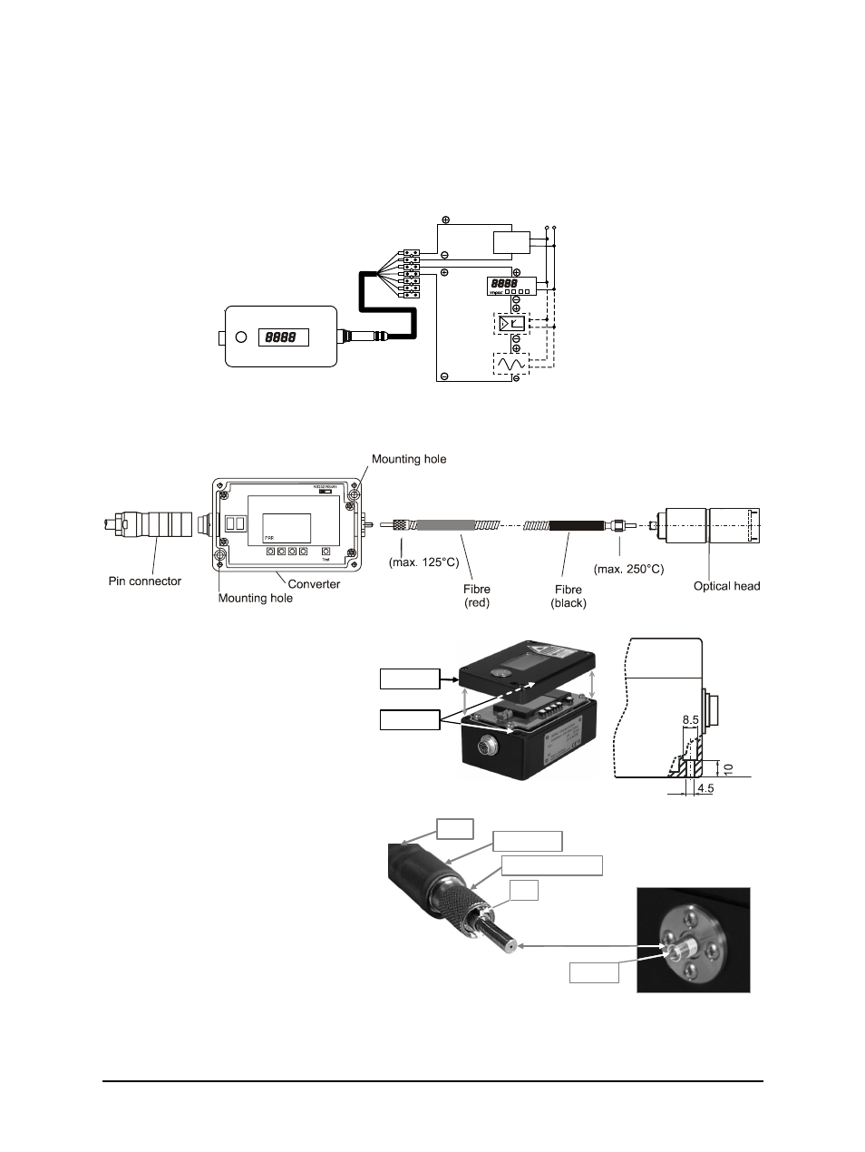
3.1.3 Connection of additional analyzing devices
Additional analyzing instruments (such as LED digital display instruments) only need to be
connected to a power supply and the analog outputs from the pyrometer. Another Instrument,
such as a controller or printer, can be connected to the display in series as shown below (total
load of resistance max. 500 Ohm).
yellow
LED digital display
Controller
Power supply
green
brown
white
230 V ~
24 V DC
°C
Writer
Converter
3.2 Mechanical Installation
3.2.1 Overview
3.2.2 Converter
To fix the converter, 2 drill holes for
screws with 4 mm diameter
accessible after removing the cover.
For fixing and aligning the optical
head, different mounting supports
are available (see 2.6 Accessories
(option)).
3.2.3 Fiber
The transmission between optical head
and converter is done via 0.2 mm (red
fiber mark) mono fiber with a stainless
steel protection hose (exceptions:
IS 50-Si-LO plus, MB 13: 0.4 mm mono
fiber (blue mark) and IS 50-Al-LO plus:
0.6 mm mono fiber (green mark)). The
optical head contains only the lens, the
sensor and the electronics are located
in the converter. Fiber and optical head
can be used in ambient temperatures
up to 250 °C without additional cooling (fiber at converter side max. 125 °C).
Cover
Drill holes
Fibre
Screw connection
Pin
Cut-out
Red mark