Warning – Hired-Hand Feed Management System User Manual
Page 8
Part No. 4801-2998 Rev 6-04
FEED MANAGEMENT SYSTEM
Page 8 of 15
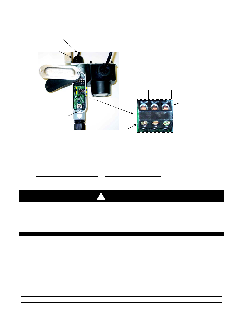
9. Close the enclosure cover, place the rubber seal, and tighten the enclosure bottom screw securely by hand.
Do not over tighten.
8.2
Feed Level Sensor Mounting
Tools and Parts Required For This Section:
Drill
7/16” Wrench
¼-20 x ½” Bolt
Qty = 2
¼” Drill Bit
7/16” Ratchet
¼-20 Nylon Lock Nut
Qty = 2
WARNING!
• Proper safety equipment must be used during installation of Feed Level Monitor.
• Do not install or maintain equipment during a lightning storm.
Failure To Follow These Instructions May Result In Property Damage,
Serious Injury, Or Death.
Mounting Requirements: The Feed Level Sensor should be mounted approximately 45° away from the feed bin
cover hinge as shown in Figure 5. Sensor placement and securing the 3 conductor
cable should help prevent accidental contact during feed replacement.
1. Select the location for mounting the Feed Level Sensor. The mounting location should be 45° to either
side of the feed bin cover hinge. Refer to Figure 5.
2. Carefully hang the Feed Level Sensor over the feed bin flange as shown in Figure 6. Mark the location for
the top bolt hole and remove the sensor. Use a ¼” drill bit and drill the marked hole location through the
feed bin cover flange.
!
Gnd Sig Vdc
Strip wires ¼”
and place inside
appropriate slot.
Dome-Shaped Nut
Sensor Cable
Tighten screws onto
bare conductors.
Enclosure
bottom screw.
F
F
i
i
g
g
u
u
r
r
e
e
4
4