Feed level sensor installation – Hired-Hand Feed Management System User Manual
Page 7
Part No. 4801-2998 Rev 6-04
FEED MANAGEMENT SYSTEM
Page 7 of 15
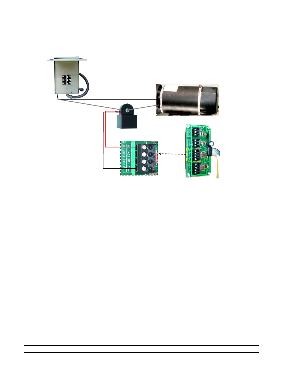
7.1 Sensor Connection to Motor Wires and Feed Management I/O Module
The current sensor must be within 9 feet of the control. The sensor may be placed inside the control or breaker box.
The wires from the Current Sensor to the Feed Management I/O Module should be shielded, twisted pair, 20 AWG
minimum (HHI P/N: 1503-2427 must be ordered separately).
8. Feed Level Sensor Installation
The Feed Level Sensor is an ultrasonic sensor designed to monitor the feed level inside a feed bin.
8.1
Feed Level Sensor Wiring
Wiring Requirements: A customer supplied shielded, 3 conductor, 20 AWG minimum cable must be used to run
from the top of the feed bin to the Evolution controller. (HHI P/N 1503-2963 cable must
be ordered separately.)
1. Loosen the enclosure bottom screw and open the enclosure cover.
2. Observe the orientation of the 3-pin connector and remove the connector from the PCB header. Refer to
Figure 4.
3. Loosen the dome-shaped nut from around the existing sensor cable and run the customer supplied cable
first through the supplied cable sleeve then through the dome-shaped nut and into the enclosure. Use care
to prevent damage to existing sensor wire connections.
NOTE: The cable protection sleeve must be placed over the 3 conductor cable at this point although will
remain loose until the Feed Level Sensor is mounted and secured in the Feed Sensor Mounting section.
4. Strip the three-conductor cable wires ¼”.
5. Insert the three wires into the 3-pin connector slots and tighten the three screws securely by hand. Do not
over tighten.
6. Place the 3-pin connector onto the PCB header in the same orientation as removed while taking some of
the slack out of the 3-conductor cable. Do not stress the wires or connector by pulling wires or cable
excessively tight.
7. Tighten the dome-shaped nut securely around the cables.
8. IMPORTANT: Record the wire colors to each of the 3 connections (Gnd, Sig, & Vdc) and retain for
connections to the Evolution controller’s Feed Management I/O Module.
Breaker Box
Current
Sensor
Feed Auger / Belt / Other Motor
L2
L1
Feed
Management
I/O Module
Black
Red
Com
AG1
F
F
i
i
g
g
u
u
r
r
e
e
3
3