Hired-Hand Feed Management System User Manual
Page 12
Part No. 4801-2998 Rev 6-04
FEED MANAGEMENT SYSTEM
Page 12 of 15
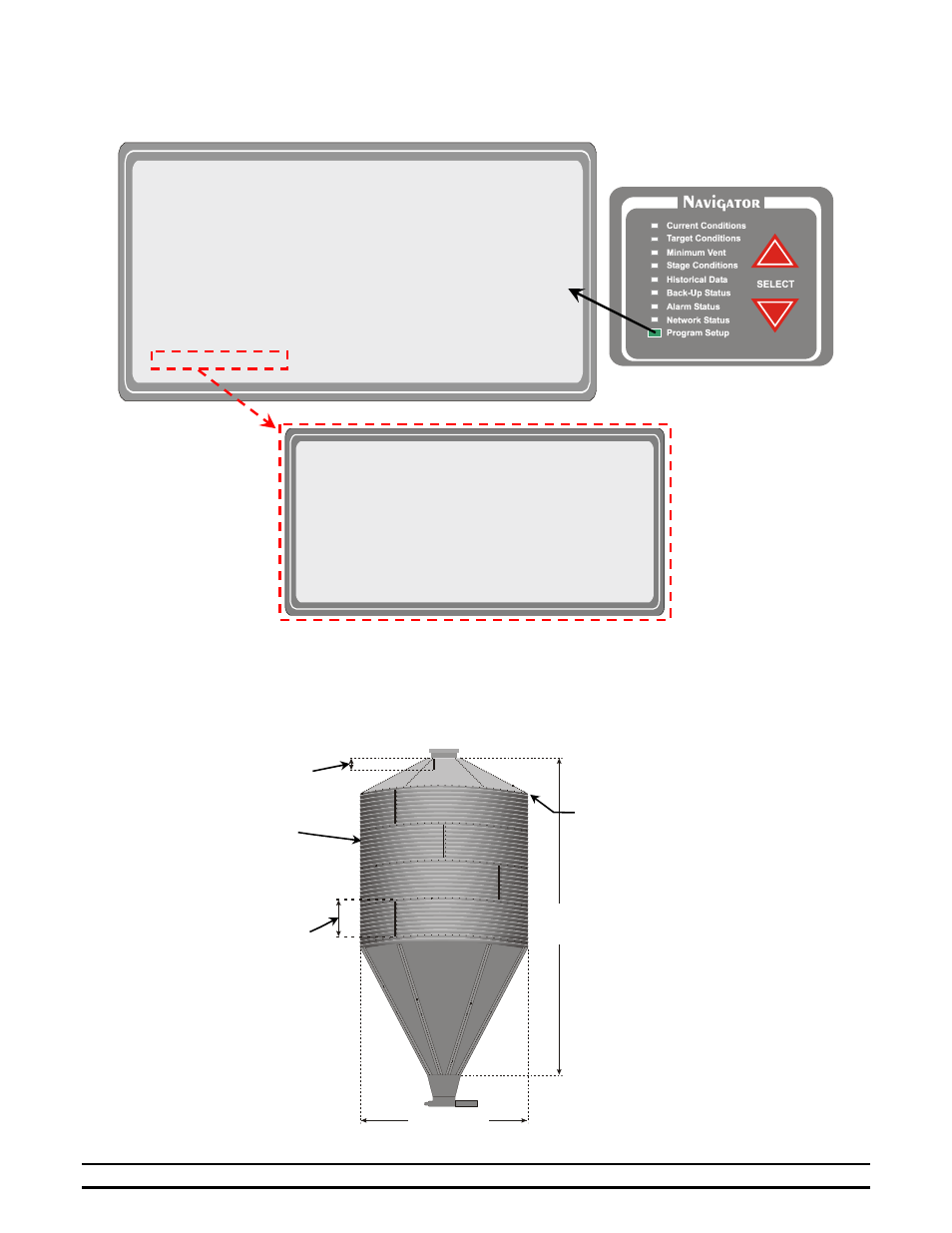
For the Ultrasonic Feed Level sensors, we have created a Setup Wizard that allows the installer easy setup. The
following screen shows the Feed Level Setup Wizard screen.
The user enters the “Bin Diameter” (6’, 7’, 9’, or 12’), the “Cap Angle” (30 or 40 degree), the “# of Rings” (1 –
5), and the “Ring Height” which should typically be 2.67’ (2’ 8”). The “Ring Height” can be used to adjust any
errors in calculation that the controller might make. The EV will then calculate the “Bin ht” (Bin Height). You can
verify this by measuring from the top of the boot to the top of the cap (excluding the lid ring). Refer to Figure 10.
If the “Bin ht”, is incorrect, adjustments can be made to the “Ring Height” for correction. In addition, “Feed wt.”
displays the estimated weight of the feed currently in the bin based on a feed density of 40 lbs/cu. ft.
** Feed Level Module Setup **
(1)Bin 1:
(2)Diameter = 6 ft
(3)Cap Angle = 30°
(4)# of Rings = 1
(5)Ring Height = 2.67ft
(6)Feed wt: 00 lb (7)Bin ht: 9.07 ft
(8)Bin 2:
(9)Diameter = 6 ft (10)Cap Angle = 30°
(11)# of Rings = 1 (12)Ring Height = 2.67ft
(13)Feed wt: 00 lb (14)Bin ht: 9.07 ft
** FREQUENTLY ADJUSTED SETTINGS **
"
(1)GENERAL SETTINGS (3)STATIC PRESSURE
(2)SENSOR SETUP (4)PROGRAMS & SECURITY
** INITIAL SETUP **
(5)TEMP/TIMER% RAMP (12)TUNNEL SETUP
(6)FEED CLOCK SETUP (13)ON/OFF STAGES 1-16
(7)LIGHT CLOCK SETUP (14)ON/OFF STAGES 17-32
(8)STAGE PROPERTIES (15)ON/OFF STAGES 33-48
(9)NATURAL VENT (16)ON/OFF STAGES 49-64
(10)DIAGNOSTICS (17)VARIABLE
STAGES
(11)FEED LEVEL
Top Angle
Bin
Height
Ring
Height
Diameter
Number of
Rings
Dead Zone
F
F
i
i
g
g
u
u
r
r
e
e
1
1
0
0