Hired-Hand Feed Management System User Manual
Page 6
Part No. 4801-2998 Rev 6-04
FEED MANAGEMENT SYSTEM
Page 6 of 15
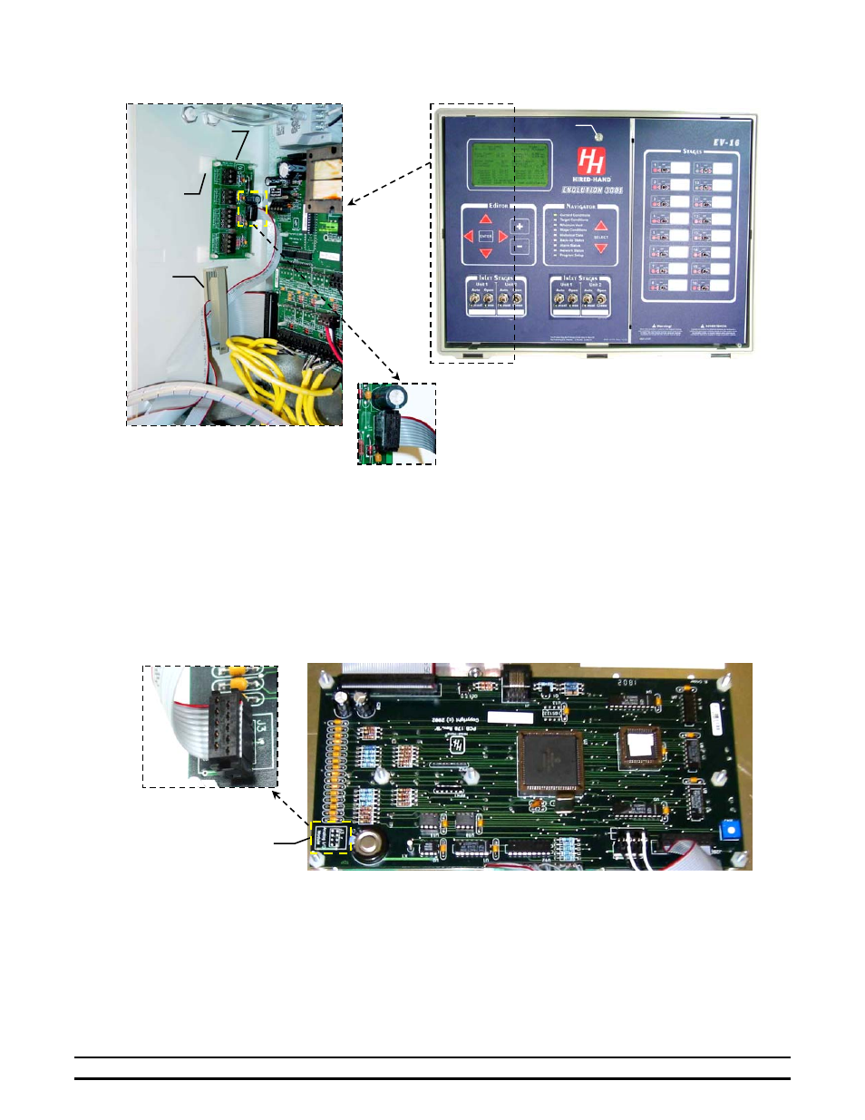
4. Remove the paper backing from the standoff double-sided tape attached to the I/O Module and apply the
I/O Module to the inside, left side of the enclosure as shown in Figure 1. Ensure that the I/O Module is
not placed excessively low which will prevent ribbon cable removal OR excessive high which may contact
the front panel circuit boards and interfere with closure of the control front panel.
NOTE: The standoff tape is difficult to remove once applied to the enclosure surface. Ensure the I/O
Module is positioned properly before making contact with the enclosure.
5. Route the ribbon cable through the ribbon cable holder and connect the remaining end of the ribbon cable
to PCB 170 in the orientation shown in Figure 2. Ensure the ribbon cable is placed and secured so that it
can not be pinched during closure or opening of the front panel.
6. Ensure all wires are out of the front panel hinge and closure areas, close the front panel, and secure with
the front panel screw.
7. Current Sensor Installation on Feed Augers or Egg Belts
The Current Sensor is designed to provide an ON-OFF indication of current flow. Current levels above .35 Amps
turn the switch ON. This Current Sensor is recommended only for applications with a continuous operating current
above .35 Amps. The Current Sensor will not turn completely ON if the application has a current level below .35
Amps.
Front Panel Screw
Feed Management
I/O Module
Standoffs &
Double-
Sided Tape
Ribbon
Cable
Holder
F
F
i
i
g
g
u
u
r
r
e
e
1
1
I/O Module
Connection
P
P
C
C
B
B
1
1
7
7
0
0
F
F
i
i
g
g
u
u
r
r
e
e
2
2