Feed management software programming – Hired-Hand Feed Management System User Manual
Page 11
Part No. 4801-2998 Rev 6-04
FEED MANAGEMENT SYSTEM
Page 11 of 15
9. Feed Management Software Programming
This section introduces the Feed Management software. The Evolution controller software allows the use of two
ultrasonic feed level sensors and two current sensors. The feed level sensors are used to monitor the feed inventory
in the feed bins. The current sensors are used primarily to monitor the runtime of the cross-fill auger motors. The
following screen shows the Evolution controller 100 day Feed History that is generated through the use of these
sensors. The Usage column shows the daily estimated usage in lbs., or kg. The Auger1 and Auger2 columns
display the daily runtimes for the current sensors (hours: minutes). Notice that the first row indicates the present
status of the current sensors.
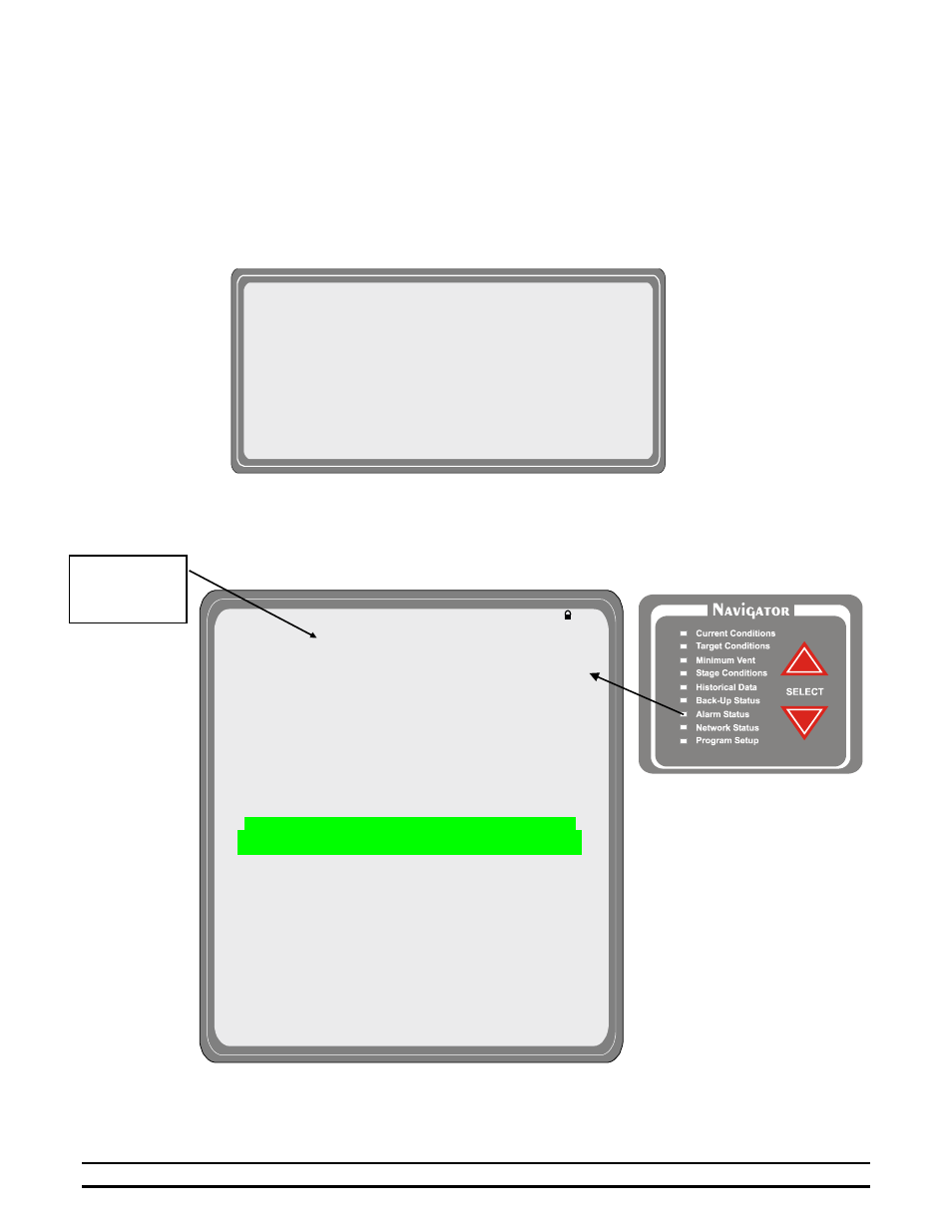
In addition to the history capabilities, the addition of the current sensors adds two new alarm features. The alarms
allow you to place a runtime limit on each current sensor to help the user detect feed spills or protect against
running out of feed. The updated Alarm Status screen is shown below.
(1)Day (2)Usage
(3)Auger1
(4)Auger2
(5)Status
On
On
41
2100
lb
4:10
9:10
40
2000
lb
3:00
8:00
.
.
.
.
35
1500
lb
3:00
8:00
.
.
.
.
.
.
.
.
24
1000
lb
1:30
6:30
.
.
.
.
.
.
.
.
1
150
lb
1:10
6:10
"
TEMPERATURE LIMIT STATUS LAST ALARM
(1)High Temp 85.0
°
OK 08/15-10:36p
(2)Low Temp 65.0
°
OK
08/10-03:36p
PRESSURE LIMIT STATUS LAST ALARM
(3)Cycle Press 0.04 Off 08/09-07:36p
(4)High Press 0.15 Off 07/22-01:36p
(5)Low Press 0.03 Off 07/13-06:36p
WATER ALARMS LIMIT STATUS LAST ALARM
(6)High Rate #1 100/hr OK 01/01-12:00a
(7)Low Rate #1 25/hr OFF 01/01-12:00a
(6)High Rate #2 100/hr OK 01/01-12:00a
(7)Low Rate #2 25/hr OFF 01/01-12:00a
FEED ALARMS LIMIT STATUS LAST ALARM
(8)Auger Run1
10min OFF
01/01-12:00a
(9)Auger Run2
10min OFF
01/01-12:00a
SYSTEM STATUS STATUS
LAST ERROR
(10)Tunnel Vent ---- OK
07/12-02:36p
(11)Growout Day ---- OK
07/31-05:36p
(12)Local Network --- OK
07/27-05:36p
(13)Back-Up Limits -- OK
07/31-05:36p
(14)Sensor 1 ---- OK
07/27-05:36p
(14)Sensor 2 ---- OK
06/10-09:36p
(14)Sensor 3 ---- OK
06/11-01:36p
(14)Sensor 4 ---- OK
06/13-06:36p
(14)Sensor 5 ---- OK
06/13-03:36p
(14)Sensor 6 ---- OK
06/21-03:36p
(14)Sensor 7 ---- OK
06/17-02:36p
(14)Sensor 8 ---- OK
06/13-10:36p
(15)Outside ---- OK
07/13-02:31p
NOTE: The High and Low
temperature reading is taken from
the Sensors for Display in “Sensor
Setup” of the Program Setup
Screen.
Proceed
to Detail
Screens