Condec UPC5010 User Manual
Page 9
6
UPC5000/UPC5010 Operation & Maintenance Manual
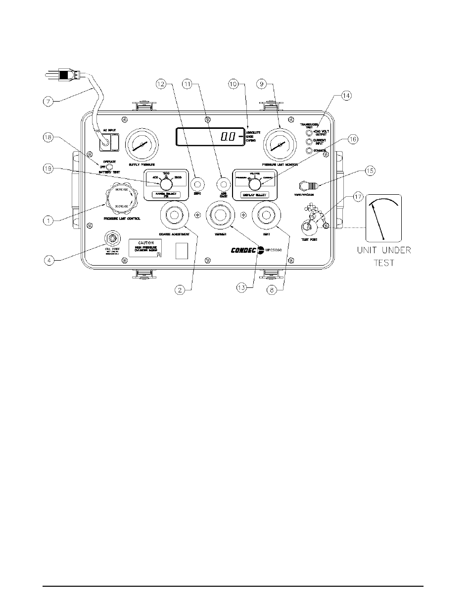
Figure 2-3. Pressure Measurement Sequence (Gage Only)
NOTE
:
UPC5000 shown, AC Input (7) and Fill Port (4) are on back side of UPC5010 Rack Mountable Calibrator.
2.5
Pressure Measurement Sequence for Absolute Only Unit
1. If only pressure measurements greater than barometric are required, continue to step 1.1. If pressure
measurements above and below atmospheric pressure are required, go to Step 2.
1.1.
To apply pressure, close the
VENT
valve (8) (approximately two turns to its stop) and open the
COARSE ADJUSTMENT
valve (2) approximately 1/2 turn counter-clockwise until the numerical
display begins to move. In general, the pressure may be changed rapidly until reaching
approximately 90% of its desired final value.
1.2.
Use either the
COARSE ADJUSTMENT
(2) or
VENT
valve (8) to obtain a specific pressure reading.
Both provide precise control. As the pressure approaches the desired value, the valve being used for
control should be rotated slowly clockwise to its closed position.
1.3.
To obtain exact pressure readings, slowly rotate the
VERNIER
control (13) knob in the direction
required (clockwise to increase pressure) as indicated by the electronic numerical display.
2. If pressure measurements above and below atmospheric pressure are required, connect a vacuum pump
to the
VACUUM/VENT
port (15) as shown in Figure 2-4 on page 7.
3. Open the
VENT
valve (8), close the
COARSE ADJUSTMENT
valve (2) and apply power to the vacuum
pump and allow it to evacuate the system for several minutes or until the digital display reading reaches
equilibrium near zero PSIA. Press the
ZERO
button to establish a zero reference on the display.
4. With the vacuum pump still running, close the
VENT
valve (8) and check for system leaks. If there are
none, continue to step 4.1.
4.1.
To apply pressure, close the
VENT
valve (8) (approximately two turns to its stop) and open the
COARSE ADJUSTMENT
valve (2) (approximately 1/2 turn counter-clockwise until the numerical
display begins to move). In general, the pressure may be changed rapidly until reaching
approximately 90% of its desired final value.