Condec UPC5010 User Manual
Page 32
Maintenance and Service
29
2. Install the new switch, lock washer and nut through the panel rear. Hand tighten the trim ring from front
of panel.
3. Tighten the switch mounting nut and lock washer from the rear of panel. Replace CPU if necessary.
If wrench is used, do not over tighten, damage may occur to switch.
4. Install panel/chassis assembly in its enclosure as described in Section 4.2.1 on page 14.
4.2.26
Power Supply Assembly, Removal and Installation (Battery Units)
120 VAC input (PN 58723); 220 VAC input (PN 58729).
Tools required:
Phillips screwdriver
Flat blade screwdriver (small)
11/32" open end wrench or nutdriver
Removal of Power Supply Board
1. Disconnect the power cord from the power source and line filter. Remove front panel from its enclosure,
as described in Section 4.2.1 on page 14, and carefully set on a bench top.
2. Disconnect the three wire connectors (black, white, green) that are between the AC filter cable (PN
55540) and the cable attached to the power supply board assembly.
3. Unplug the multi-pin connector of the CPU (J6) to power supply (J1) cable (PN 55023) from the power
supply board.
4. Remove the two battery cable wires (PN 56367) from the terminal block (TB1) on the power supply
board.
5. Loosen and remove the four nuts that hold the power supply board and remove the board.
Installation of Power Supply Board
1. Position the new board over the four standoffs and install four nuts. Tighten the nuts until snug.
2. Install the two battery cable wire ends into the terminal block (TB1) on the power supply board, red wire
(+) to TB1-3 and black wire (-) to TB1-1.
3. Plug the CPU (J6) to power supply cable (PN 55023) connector into the power supply board (J1).
4. Connect the three connectors (black, white, green) of the AC filter cable (PN 55540) and the cable from
power supply board assembly. Connect like wire colors together.
5. Install panel/chassis assembly in its enclosure as described in Section 4.2.1 on page 14.
4.2.27
Battery (Replacement Kit PN 55354) Removal, Installation and Adjustments
Tools required:
Phillips screwdriver
Flat blade screwdriver (small)
11/32" open end wrench or nutdriver
Removal:
1. Disconnect the power cord from the power source and line filter. Remove front panel from its enclosure
as described in Section 4.2.1 on page 14, and carefully set on a bench top.
2. Disconnect the two battery cable wires (PN 56367) from the battery terminals, red wire from (+) and
black wire from (-).
3. Remove the two nuts and two screws that secure the battery bracket (PN 58386).
4. Remove the bracket and battery.
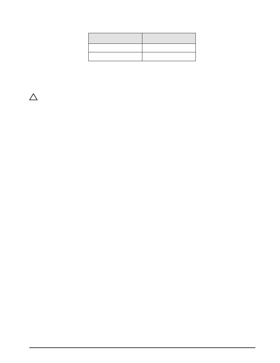
Color
Terminal
Yellow
Normally open
Green
(C) common
Table 4-6. Wire to switch terminal connections: Zero
!
Caution