2 initial setup procedure – Condec UPC5010 User Manual
Page 7
4
UPC5000/UPC5010 Operation & Maintenance Manual
2.2
Initial Setup Procedure
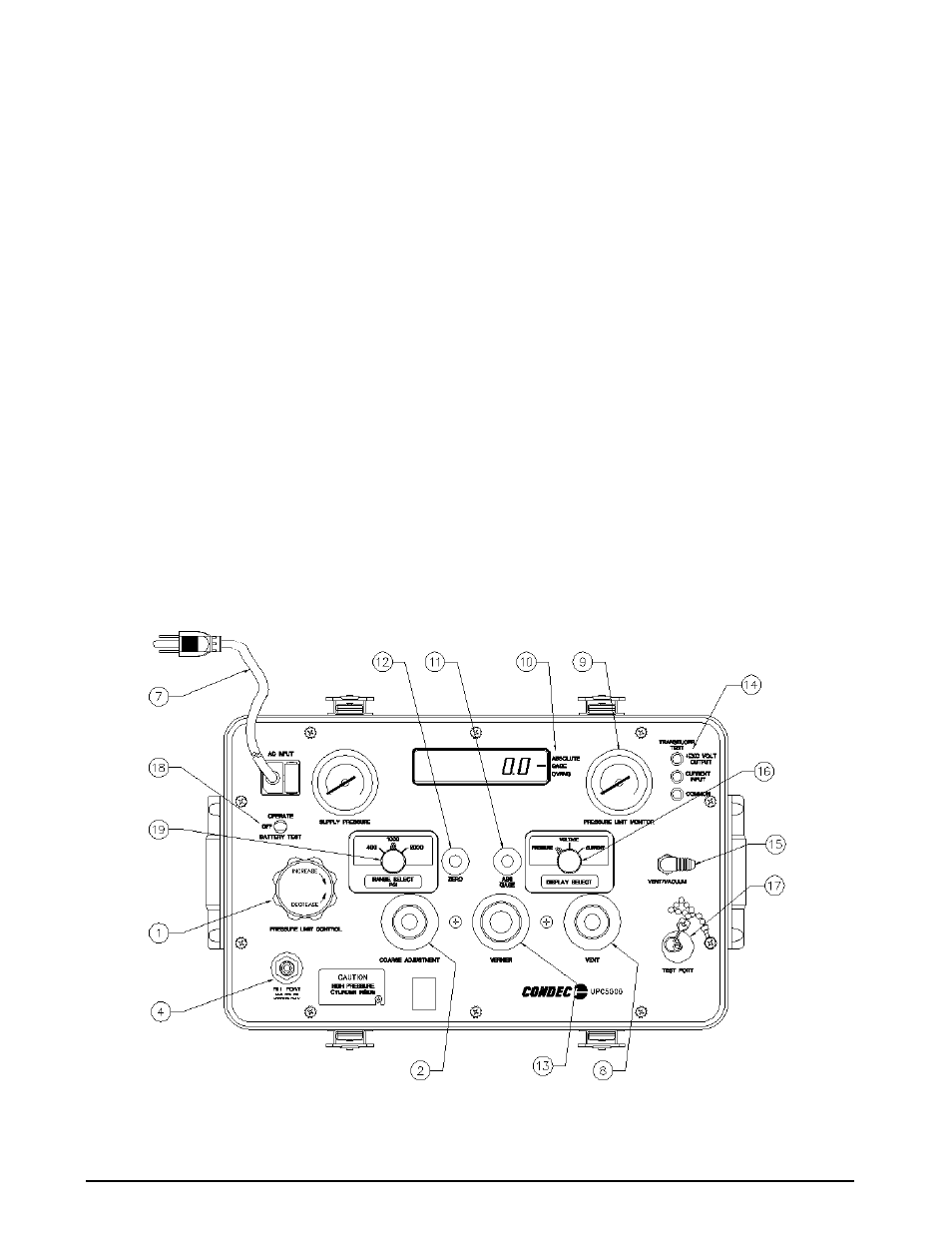
To prepare for actual calibration usage, see Figure 2-2 below and proceed as follows:
1. Check that the
COARSE ADJUSTMENT
valve (2) is closed (rotate clockwise until it stops) and that the
VENT
valve (8) is open (two turns counter-clockwise from its stop).
2. Plug in the power cord (7) and energize the unit by flipping the power switch (18) to
OPERATE
. The
UPC5000/UPC5010 will perform an internal functional self-check. If acceptable, a 100.00 flashes briefly
and the display returns to a normal reading. Allow at least ten minutes warm-up time, then zero unit by
momentarily depressing the ZERO switch (12) for less than five seconds. The instrument can be zeroed
at any time, as long as the VENT valve (8) is open, by momentarily depressing the ZERO switch (12) for
less than five seconds.
NOTE:
If ZERO switch is depressed longer than 5 seconds unit will perform an internal functional self-check.
3. Select the desired full scale pressure range via the three-position
RANGE SELECT
rotary switch (19).
For the best accuracy, the selected range must be greater than, but close as possible to, the full scale
range of the device under test.
NOTE:
Do not switch pressure ranges during a calibration cycle.
4. Using the
PRESSURE LIMIT CONTROL
regulator (1), adjust the maximum system input pressure (as read
by the
PRESSURE LIMIT MONITOR
[9]), to any desired value higher (typically 20–50% higher) than the
full-scale range of the device under test. Using this technique, the device under test is fully protected
from being accidentally over-pressurized.
5. Set the
DISPLAY SELECT
switch (16) to the
PRESSURE
position.
6. Connect the male end of the test hose to the
TEST PORT
(17) fitting.
7. Connect the swivel fitting end (7/16-20) of the test (output) hose to the device-under-test (use adapters if
required). Tighten all connections properly.
Figure 2-2. Initial Setup Procedure
NOTE
:
UPC5000 shown, AC Input (7) and Fill Port (4) are on back side of UPC5010 Rack Mountable Calibrator.