4 pressure measurement sequence for gage only unit – Condec UPC5010 User Manual
Page 8
Operation
5
8. Optional - if the current (4.000 to 20.000 mA) measurement features are used, connect the provided
transducer test cable, (PN 55092), to the transducer test jacks (14).
When connected, the transducer test cable provides +32 VDC excitation on non-battery units, or +18 VDC
excitation on battery units. The internal impedance (load) is 10 ohms.
NOTE:
+ EXCITATION VOLTAGE will only operate while units power cord is plugged into AC wall outlet. Battery units
may be ordered special to obtain +28 VDC excitation.
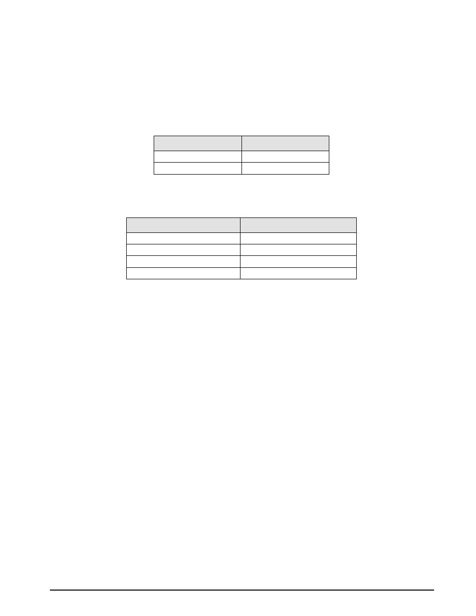
The display scaling for these current measurements are as follows:
NOTE:
UPC5000/UPC5010 reads a 4-20 mA signal only, but will display as either 4-20 mA or 20-100 mV.
The test cable connector wiring is as follows:
NOTE:
Connector pin designations are for reference only, and are no longer a connector on newer units. See Figure 2-2
on page 4 (14).
2.3
Pressure Measurement Sequence for Absolute/Gage Unit
1. Check that the indicator on the right end of the display indicates desired mode (10). If not, momentarily
depress the ABS/GAGE switch (11) to obtain mode.
2. If operating unit in GAGE mode go to Section 2.4. If operating unit in ABSOLUTE mode go to Section
2.5.
2.4
Pressure Measurement Sequence for Gage Only Unit
NOTE:
See Figure 2-3 on page 6 when following these steps.
1. To apply pressure, close the
VENT
valve (8), approximately two turns, until it stops, then open the
COARSE ADJUSTMENT
valve (2) approximately 1/2 turn counter-clockwise until the numerical display
begins to move. The pressure may change rapidly until reaching approximately 90% of the desired final
value.
2. Use either the
COARSE ADJUSTMENT
(2) or
VENT
valve (8) to obtain a specific pressure reading. Both
provide precise control. As the pressure approaches the desired value, the valve being used for control
should be rotated slowly clockwise to its closed position.
3. To obtain exact pressure readings, slowly rotate the
VERNIER
control (13) knob in the direction required
(clockwise to increase pressure) as indicated by the electronic numerical display.
4. The transducer current measurement can be displayed at any time by placing the
DISPLAY SELECT
switch (16) to its
CURRENT
position.
SWITCH POSITION
DISPLAY READING
Current
0-20.000 mA by 0.005 mA
*
Voltage
0-100.00 mV by 0.02 mV
Table 2-1. Display Select Switch (16)
CONNECTOR PIN DESIGNATION
FUNCTION
A
+ VDC
B
+ SIGNAL
C
NOT USED
D
VOLTAGE & SIGNAL COMMON
Table 2-2. Transducer Test Cable (PN 55092)