3 zero/span calibration, 4 linearity and hysteresis calibration – Condec UPC5010 User Manual
Page 12
Calibration
9
3.3
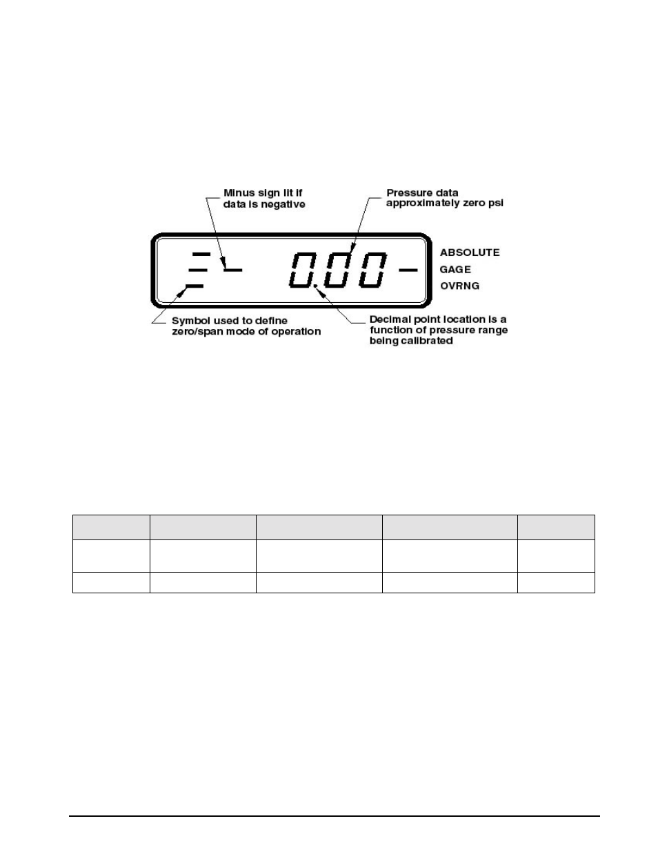
Zero/Span Calibration
Selecting the
ZERO/SPAN
position on the Condec Calibration Module (PN 60109) places the instrument into its
ZERO/SPAN
calibration mode. The display is shown in Figure 3-2.
NOTE:
Absolute Only Unit requires vacuum pump with PSIA indicator to obtain readings below local barometric
pressure.
Figure 3-2. Zero/Span calibration for Absolute/GageUnit
Starting with the instrument’s lowest pressure range, perform Steps 1 and 2 shown in Table 3-1 for each pressure
range.
Note:
Perform Step 1 in all ranges prior to doing Step 2.
Perform the following for each step:
1. Gage Only or Absolute/Gage Unit: Adjust input pressure to the appropriate (either 0 or 100%) value.
Absolute Only Units: Must use a vacuum pump with PSIA display, to reach as close to 0 PSIA as
possible.
2. Perform the action indicated in Table 3-1 when pressure input readings are stable.
NOTES:
1.
If readings are not stable or are not within ±20% of zero, the zero correction can’t be entered.
2.
If readings are not stable or are not within ±5% of 100%, the span correction cannot be entered.
3.
Absolute only unit: Maximum vacuum standard display reading of 0.04 PSIA.
3.4
Linearity and Hysteresis Calibration
Install the Condec Calibration Module (PN 60109) and select the
LYN/HYS
position of the rotary switch on the
module. This places the UPC5000/UPC5010 into its linearization/hysteresis calibration mode. The display is
shown in Figure 3-3 below.
NOTE:
The zero/span calibration needs to be performed prior to linearity and hysteresis calibration. For Absolute Only
Unit, vacuum pump with PSIA indicator must be used to obtain readings below local barometric pressure.
Step No.
Pressure Input Value
Operator Action Required
Resulting Display Indication
Remarks
1
0% (see Note 3
below)
Press ENTER
button
0%
Note 1 below
2
100%
Press ENTER button
100%
Note 2 below
Table 3-1. Zero and Span Calibration Sequence