Signal wiring of the mx100 – Yokogawa PC-Based MX100 User Manual
Page 15
15
IM MX100-0E
Signal Wiring of the MX100
For a description of the installation procedure, module attachment procedure, signal
wiring details, and wiring of the power supply, see the MX100/MW100 Data Acquisition
Installation and Connection Guide (IM MX100-72E) or the MX100 Data Acquisition Unit
User’s Manual (IM MX100-01E). For the safety precautions, see the Precautions on the
Use of the MX100/MW100 Data Acquisition Unit (IM MX100-71E) or the MX100 Data
Acquisition Unit User’s Manual (IM MX100-01E).
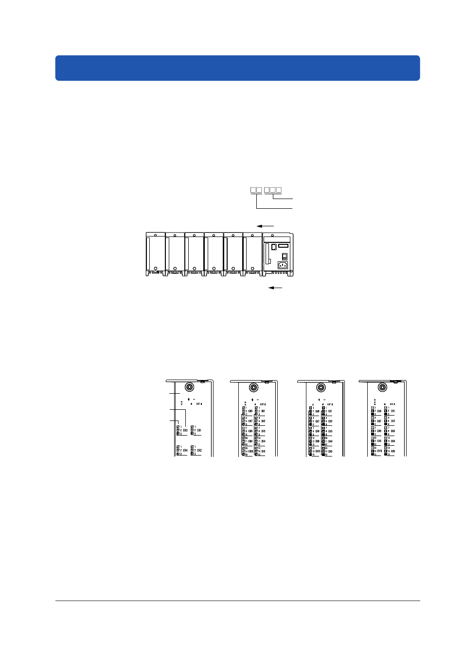
Attachment Position and Channel Numbers of the Input/Output Module
The figure below shows how the MX100 Standard Software identifies the channel
numbers.
MX100
0
1
2
3
4
5
Slot number
001 to 010
011 to 020
021 to 030
031 to 040
041 to 050
051 to 060
Channel number in the unit
*2
Representation of channel numbers:
Channel numbers in a unit (001 to 060)
Unit number (00 to 19)
*1
*2 The last one digit on a 4-channel module is 1 to 4.
The last one digit on a 6-channel module is 1 to 6.
The last one digit on a 8-channel module is 1 to 8.
*1 When connecting to the module
using the MX100 Standard
Software, the number is
fixed to 00.
Terminal Arrangement Markings on the Terminal Cover
On the rear side of the terminal cover of each input/output module are characters that
indicate the functions of the terminals and terminal symbols. Connect the wires according
to the markings. The figure below is an example only.
100Vpk MAX TO
250V MAX CH TO CH
600V MAX TO
100Vpk MAX TO
120V MAX CH TO CH
600V MAX TO
250V MAX CH TO CH
250V MAX NO TO C
250V MAX TO
10Vpk MAX TO
250V MAX TO
4-CH, High-Speed
Universal Input Module
10-CH, Medium-Speed
Universal Input Module
10-CH, High-Speed
Digital Input Module
Channel number
in the module
Terminal symbol
10-CH, Medium-Speed
Digital Output Module
Terminal cover