Yokogawa DO402 Dissolved Oxygen Analyzer User Manual
Page 80
IM 12J05D02-01E
8-2 Troubleshooting
8-2. Measures in the case of failure (Error) detection
If a failure is detected through the self-diagnosis of the DO402G dissolved oxygen converter, the FAIL
contact is closed. The FAIL lamp on the operation panel lights up and an error number appears in the
data display.
Note:
If an error is detected during configuration, the FAIL contact signal is output immediately but the
error number is displayed after that action or operation is completed.
When a FAIL contact signal is output, take measures according to Table 8-1.
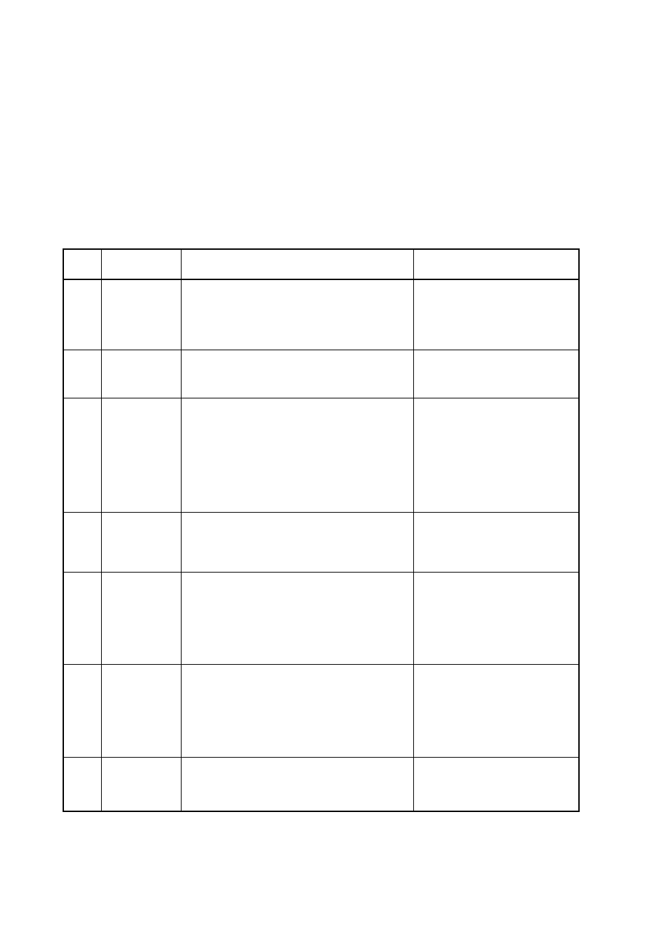
Table 8-1.
Countermeasures in the case of failure (Error) detection
Error
No.
Generation
Mode
Error Content and Causes
Countermeasures
E1
AIR.CAL mode
H2O. CAL mode
Stability failure
Even after an hour has elapsed, the measured value
change does not decrease within the set value of (mg/l)
• Sensor temperature changes.
• Dissolved-oxygen of the calibration solution changes.
• The value of A (mg/l) is not suitable.
Eliminate the causes and press the
(NO) key to perform re calibration.
E2
H2O. CAL mode
Zero point error failure
The zero point error exceeds the set range
• Dirt sticks to the tip of the sensor.
• Membrane abnormality. Electrolyte degradation.
Clean the sensor membrane, sensor
cap, and recalibrate. If the error is
detected again, replace the electrolyte
and the membrane, sensor cap.
E3
AIR.CAL mode
H2O. CAL mode
MAN.CAL mode
Slope failure
The slope exceeds the range of 40 to 200 % of the
theoretical value.
• Dirt sticks to the tip of the sensor.
• Membrane abnormality. Electrolyte degradation.
Clean the sensor membrane, sensor
cap, and recalibrate. If the error is
detected again, replace the electrolyte
and the membrane. Check that the
connection between sensor and
sensor cable is fit, and LED emission
of the optical dissolved-oxygen sensor.
When error occurred again, replace
the sensor cap, sensor cable or sensor
itself.
E4
Measuring mode
Sensor membrane failure
Replace membrane
Check for wet O-rings in the
membrane assembly or wet sealing
face.
Wipe off wet areas and dry out.
E7
All modes
Measured temperature failure (too high)
It exceeds 50.0 °C (122.0 °F).
• Measuring solution temperature is high
• CODE 10 setting is not correct
• Sensor cable wiring failure
• Temperature sensor has failed
Examine the temperatures of the
measuring solution and sensor and the
CODE 10 setting
Examine the sensor cable connection
status.
If the temperature sensor fails
(abnormal resistance), replace the
sensor.
E8
All modes
Measured temperature failure (too low)
It falls below 0 °C (or 32.0 °F).
• Measuring solution temperature is low
• CODE 10 setting is not correct
• Sensor cable wiring failure
• Temperature sensor has failed.
Examine the temperatures of the
measuring solution and sensor and the
CODE 10 setting.
Examine the sensor cable connection
status.
If the temperature sensor fails
(abnormal resistance), replace the
sensor.
E9
All modes
Input current failure
It does not satisfy the following equation:
input current < 50 µA for galvanic sensor
< 500 nA for polarographic sensor and optical sensor
Examine the setting for CODE 01, 02