Installation and wiring, 1. installation and dimensions, 1-1. installation site – Yokogawa DO402 Dissolved Oxygen Analyzer User Manual
Page 21: 1-2. mounting methods, Installation and wiring -1, 1. installation and dimensions -1, 1-1. installation site -1, 1-2. mounting methods -1, Warning
IM 12J05D02-01E
Installation and wiring 3-1
3. INSTALLATION AND WIRING
3-1. Installation and dimensions
3-1-1. Installation site
This instrument is a Class A product, and it is designed for use in the industrial environment. Please use
this instrument in the industrial environment only.
The EXA converter is weatherproof and can be installed inside or outside. It should, however, be
installed as close as possible to the sensor to avoid long cable runs between sensor and converter. In
any case, the cable length should not exceed 50 meters (162 feet). For an optical dissolved oxygen sen-
sor, the allowable maximum cable length is 10 m. Select an installation site where:
• Mechanical vibrations and shocks are negligible
• No relay/power switches are in the direct environment
• Access is possible to the cable glands (see figure 3-1)
• The converter is not mounted in direct sunlight or severe weather conditions
• Maintenance procedures are possible (avoiding corrosive environments)
The ambient temperature and humidity of the installation environment must be within the limits of the
instrument specifications. (See chapter 2).
3-1-2. Mounting methods
Refer to figures 3-2 and 3-3. Note that the EXA converter has universal mounting capabilities:
• Panel mounting using optional brackets
• Surface mounting on a plate (using bolts from the back)
• Wall mounting on a bracket (for example, on a solid wall)
• Pipe mounting using a bracket on a horizontal or vertical pipe (maximum pipe diameter 50 A)
184
144
72
20
144
220
23
112
Four M6 screws, 8
(0.31)
deep
80
80
36
36
36
38
A
B
C
D
E
F
Hood (optional)
Option code : /H
□
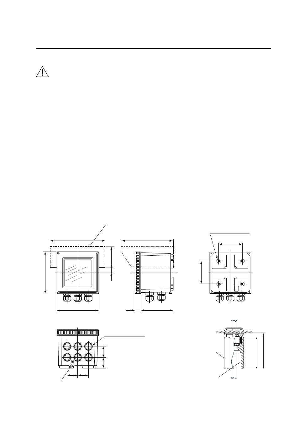
Cable inlet port (Six-21
(0.83)
dia. holes)
DIN PG13.5 cable gland
Ground terminal
(M4 screw)
Weight: Approx. 2 kg
A : Power supply for DO70G, or
contact input separately.
B : Sensor cable
C : Output signal
D : Contact output (S3 and S4)
E : Contact output (S1 and S2)
F : Power supply
Adaptor for conduit work
(option code : /AFTG, /ANSI)
Unit: mm (inch)
Approx. 55
Adaptor
G 1/2 female ( / AFTG)
1/2 NPT female ( / ANSI)
49
(7.24)
(8.66)
(3.15)
(3.15)
(1.93)
(2.17)
(5.67)
(5.67)
(2.83)
(0.79)
(0.91)
(4.41)
(1.42) (1.42)
(1.42)
(1.50)
Figure 3-1. Housing dimensions and layout of glands
WARNING