5. wiring the analog output signals, 5-1. general precautions, 5-2. analog output signals – Yokogawa DO402 Dissolved Oxygen Analyzer User Manual
Page 29: 6. wiring the standard galvanic sensor, 5. wiring the analog output signals -9, 5-1. general precautions -9, 5-2. analog output signals -9, 6. wiring the standard galvanic sensor -9
IM 12J05D02-01E
Installation and wiring 3-9
3-5. Wiring the analog output signals
3-5-1. General precautions
The analog output signals of the EXA transmit low power standard industry signals to peripherals like
control systems or strip-chart recorders (Figure 3-6).
3-5-2. Analog output signals
The output signals consist of active current signals of either 0-20 mA or 4-20 mA. The maximum load
can be 600 ohms on each.
It should be necessary to use screening/shielding on the output signal cables. Terminal 63 is used to
connect the shielding.
3-6. Wiring the standard galvanic sensor
The sensor cable has markers on the individual wires.
These markings refer to the markers on the terminals.
The temperature compensator has two wires with the markings
T1, T2 and/or 11, 12 and must be connected to terminal 11
and 12.
The measuring electrode: the cathode is marked with IE and/or 13
and must be connected to terminal 13.
The reference electrode: the anode is marked with RE and/or
15 and must be connected to terminal 15.
The liquid earth ( solution ground) is marked with 16 and must
be connected to terminal 16.
Note:
The liquid earth (solution ground) connection is valid
only when the floating ball holder, Model PB350G or
PB360G, is used. Otherwise, do not make a connection
to terminal 16. The connection, if made, may result in
abnormal readings. Even if the floating ball holder is
used, when the liquid earth (solution ground) connection is not used, then disconnect the wiring
to terminal 16. (The disconnected wire should be covered with an insulating tube to avoid contact
with other terminals.)
The overall shield of the cable is marked with 14 and must be connected to terminal 14.
Note:
A jumper cable is placed to connect converter terminals 13 and 17.
Make sure that connecting the sensor cable to the IE pin or pin 13 or pulling the sensor cable
does not cause the jumper cable to come loose. Insufficient tightening may cause unstable or
false measurements.
F0309.ai
Digital
Commnucations
12
13
15
16
63 66 65 62 61 95 94 93 92 91
SCREEN
mA2
mA1
SCREEN
TL
TL
17 11
CONT
m
A OUTPUT
14
22
21
18
SCREEN
99
SCREEN 2
23
mA Output
(IE)
(T1) (T2)
(RE)
(LE)
Short
Sensor Input
Contact
Input
Shield
Temp.
Liquid Earth
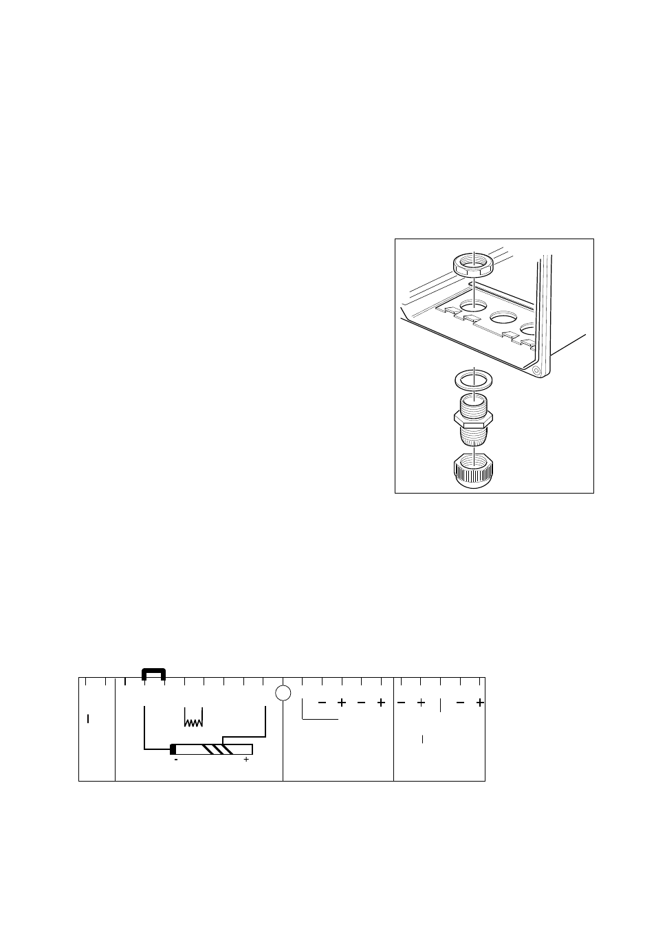
Wirning galvanic Sensor
Figure 3-11. Wirning galvanic sensor
Figure 3-10. Cable gland assembly