Yokogawa EJX115A User Manual
Page 52
<9. General Specifications>
9-6
IM 01C25K01-01E
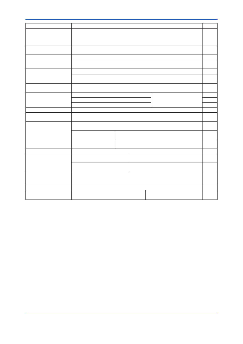
Item
Description
Code
Lightning protector
Transmitter power supply voltage:
10.5 to 32 V DC (10.5 to 30 V DC for intrinsically safe type.)
Allowable current: Max. 6000 A (1×40 μs), Repeating 1000 A (1×40 μs) 100 times
Applicable Standards: IEC 61000-4-4, IEC 61000-4-5
A
Status output *
4
Transistor output (sink type)
Contact rating: 10.5 to 30 VDC, 120 mA DC(max) Low level: 0 to 2 VDC
AL
Oil-prohibited use
Degrease cleansing treatment.
K1
Degrease cleansing treatment and with fluorinated oilfilled capsule.
Operating temperature –20 to 80°C( –4 to 176°F)
K2
Oil-prohibited use with
dehydrating treatment
Degrease cleansing and dehydrating treatment.
K5
Degrease cleansing and dehydrating treatment with fluorinated oilfilled capsule.
Operating temperature –20 to 80°C( –4 to 176°F)
K6
Capsule fill fluid
Fluorinated oil filled in capsule
Operating temperature –20 to 80°C( –4 to 176°F)
K3
Calibration units *
5
P calibration (psi unit)
(See Table for Span and
Range Limits.)
D1
bar calibration (bar unit)
D3
M calibration (kgf/cm
2
unit)
D4
Gold-plated diaphragm
Surface of isolating diaphragm is gold plated, effective for hydrogen permeation.
A1
Long vent *
6
Total length: 119 mm (standard: 34 mm); Total length when combining with
Optional code K1, K2, K5, and K6: 130 mm. Material: 316 SST.
U1
Output limits and failure
operation *
7
Failure alarm down-scale: Output status at CPU failure and hardware error is
–5%, 3.2 mA DC or less.
C1
NAMUR NE43 Compliant
Output signal limits:
3.8 mA to 20.5 mA
Failure alarm down-scale: Output status at CPU
failure and hardware error is –5%, 3.2 mA DC or less.
C2
Failure alarm up-scale: Output status at CPU
failure and hardware error is 110%, 21.6 mA or more.
C3
Stainless steel tag plate
304 SST tag plate wired onto transmitter (316 SST when /HC is specified)
N4
Data configuration at
factory *
8
Data configuration for HART
communication type
Software damping, Descriptor, Message
CA
Data configuration for BRAIN
communication type
Software damping
CB
Advanced diagnostics *
14
Multi-sensing process monitoring
• Impulse line blockage detection *
15
• Heat trace monitoring
DG6
Material certificate *
13
Cover flange, Process connector, Manifold, Orifice, and Spacer
M12
Pressure test/
Leak test certificate *
12
Test Pressure: 16 MPa (2300 psi)
Nitrogen(N
2
) Gas *
11
Retention time: one minute
T12
Contact Yokogawa representative for the codes indicated as ‘-’.
*1: Applicable for Electrical connection code 2, 4, 7, 9, C, and D.
*2: Not applicable for option code /AL.
*3:
Not applicable with color change option.
*4:
Check terminals cannot be used when this option code is specified. Not applicable for output signal code F.
*5:
The unit of MWP (Max. working pressure) on the name plate of a housing is the same unit as specified by option codes D1, D3, and
D4.
*6:
Applicable for vertical impulse piping type (Installation code 2, 3, 6, or 7) .
*7:
Applicable for output signal codes D, E and J. The hardware error indicates faulty amplifier or capsule.
*8:
Also see ‘Ordering Information’.
*9:
Not applicable for amplifier housing code 2.
*10: 316 or 316L SST. The specification is included in amplifier code 2.
*11: Pure nitrogen gas is used for oil-prohibited use (option codes K1, K2, K5, and K6).
*12: The unit on the certificate is always Pa unit regardless of selection of option code D1, D3 or D4.
*13: Material traceability certification, per EN 10204 3.1B.
*14: Applicable only for output signal code -E and -J.
*15: The change of pressure fluctuation is monitored and then detects the impulse line blockage. See TI 01C25A31-01E for detailed
technical information required for using this function.