5 troubleshooting, 1 basic troubleshooting, Troubleshooting -6 8.5.1 – Yokogawa EJX115A User Manual
Page 43: Basic troubleshooting -6, Important
<8. Maintenance>
8-6
IM 01C25K01-01E
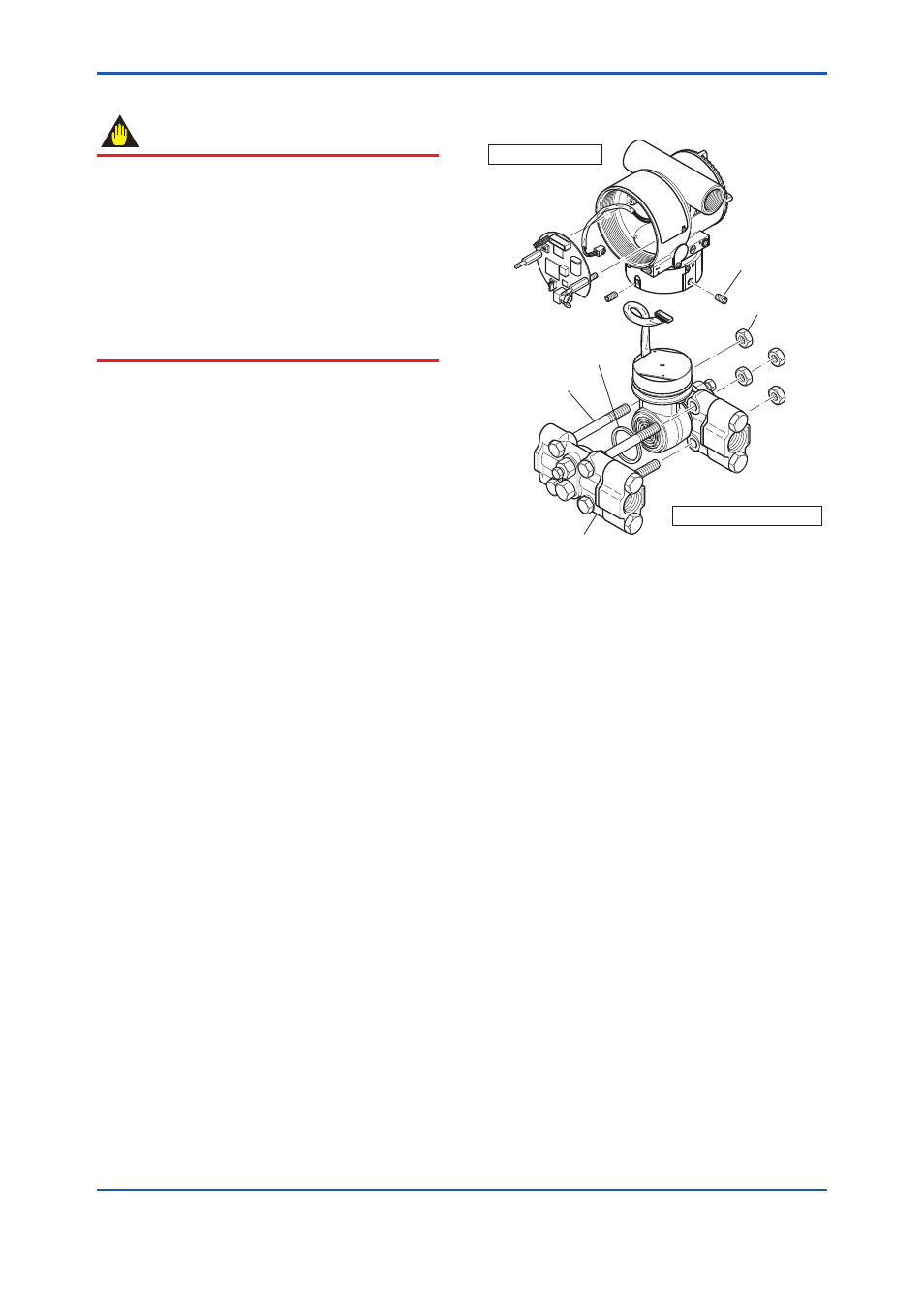
■ Removing the Capsule Assembly
IMPORTANT
Exercise care as follows when cleaning the
capsule assembly.
• Handle the capsule assembly with care, and
be especially careful not to damage or distort
the diaphragms that contact the process
fluid.
• Do not use a chlorinated or acidic solution for
cleaning.
• Rinse thoroughly with clean water after
cleaning.
1) Remove the CPU assembly as shown in
subsection 8.4.2.
2) Remove the two setscrews that connect the
transmitter section and pressure-detector
section.
3) Remove the hexagon-head screw and the
stopper.
4) Separate the transmitter section and pressure-
detector section.
5) Remove the nuts from the four flange bolts.
6) While supporting the capsule assembly with
one hand, remove the cover flange.
7) Remove the capsule assembly.
8) Clean the capsule assembly or replace with a
new one.
■ Reassembling the Capsule Assembly
1) Insert the capsule assembly between the flange
bolts, paying close attention to the relative
positions of the H (high pressure side) and
L (low pressure side) marks on the capsule
assembly.
Replace the two capsule gaskets with new
gaskets.
2) Install the cover flange on the high pressure
side, and use a torque wrench to tighten the
four nuts uniformly to a torque 17 N·m (40 N·m
for measurement span code F.)
3) After the pressure-detector section has been
reassembled, a leak test must be performed to
verify that there are no pressure leaks.
4) Reattach the transmitter section to the
pressure-detector section.
Reattach the stopper with the hexagon-head
screw.
5) Tighten the two setscrews. (Tighten the screws
to a torque of 1.5 N·m)
6) Install the CPU assembly according to
subsection 8.4.2.
7) After completing reassembly, adjust the zero
point and recheck the parameters.
F0806.ai
Transmitter section
Pressure-detector section
Cover flange
Capsule gasket
Flange bolt
Setscrew
Nut
Figure 8.6
Removing and Mounting the Pressure-
detector Section
8.5 Troubleshooting
If any abnormality appears in the measured values,
use the troubleshooting flow chart below to isolate
and remedy the problem. Since some problems
have complex causes, these flow charts may
not identify all. If you have difficulty isolating or
correcting a problem, contact Yokogawa service
personnel.
8.5.1 Basic Troubleshooting
First determine whether the process variable
is actually abnormal or a problem exists in the
measurement system.
If the problem is in the measurement system,
isolate the problem and decide what corrective
action to take.
This transmitter is equipped with a self-diagnostic
function which will be useful in troubleshooting,
and the transmitter equipped with an integral
indicator will show an alarm code as a result of self-
diagnosis.
See subsection 8.5.3 for the list of alarms.
See also each communication manual.