Operation, 1 preparation for starting operation, Operation -1 – Yokogawa EJX115A User Manual
Page 31: Preparation for starting operation -1
<7. Operation>
7-1
IM 01C25K01-01E
7. Operation
7.1 Preparation for Starting
Operation
The Model EJ115 low flow transmitter
measures the flow rates of liquids and gases. This
section describes the operation procedure for the
EJ115 as shown in Figure 7.1 (vertical impulse
piping type, high-pressure connection: right side)
when measuring a liquid flow rate.
(a) Follow the procedures below to introduce
process pressure into the transmitter.
1) Open the stop valve on the downstream side.
2) Gradually open the stop valve on the upstream
side to introduce process fluid into the
transmitter pressure-detector section.
This will cause process fluid to flow into the
orifice built in the manifold, and apply flow-
dependent differential pressure to the high and
low pressure sides of the transmitter.
3) Confirm that there are no pressure leaks in the
stop valves on the upstream and downstream
sides, process piping connection or transmitter,
etc.
(b) Venting Gas from the Transmitter Pressure-
detector Section.
Since the piping in the example of Figure 7.1
is constructed to be self-venting, no venting
operation is required. If it is not possible
to make the piping self-venting, refer to
Subsection 7.6 for instructions.
(c) Turn ON power and connect the BT200.
Open the terminal box cover, and connect the
BT200 to the SUPPLY + and – terminals.
(d) Using the BT200, confirm that the transmitter is
operating properly. Check parameter values or
change the setpoints as necessary.
If the transmitter is equipped with an integral
indicator, its indication can be used to confirm
that the transmitter is operating properly.
Stop valve(downstream side)
Stop valve
(upstream side)
Manifold
F0701.ai
Figure 7.1
Liquid Flow Measurement
Confirming that Transmitter is Operating
Properly
Using the BT200
• If the wiring system is faulty, ‘communication
error’ appears on the display.
• If the transmitter is faulty, ‘SELF CHECK
ERROR’ appears on the display.
communication error
PARAM
C60:SELF CHECK
ERROR
Communication error
(Faulty wiring)
Self-diagnostic error
(Faulty transmitter)
DATA
DIAG
PRNT
ESC
F0702.ai
Figure 7.2
BT200 Display
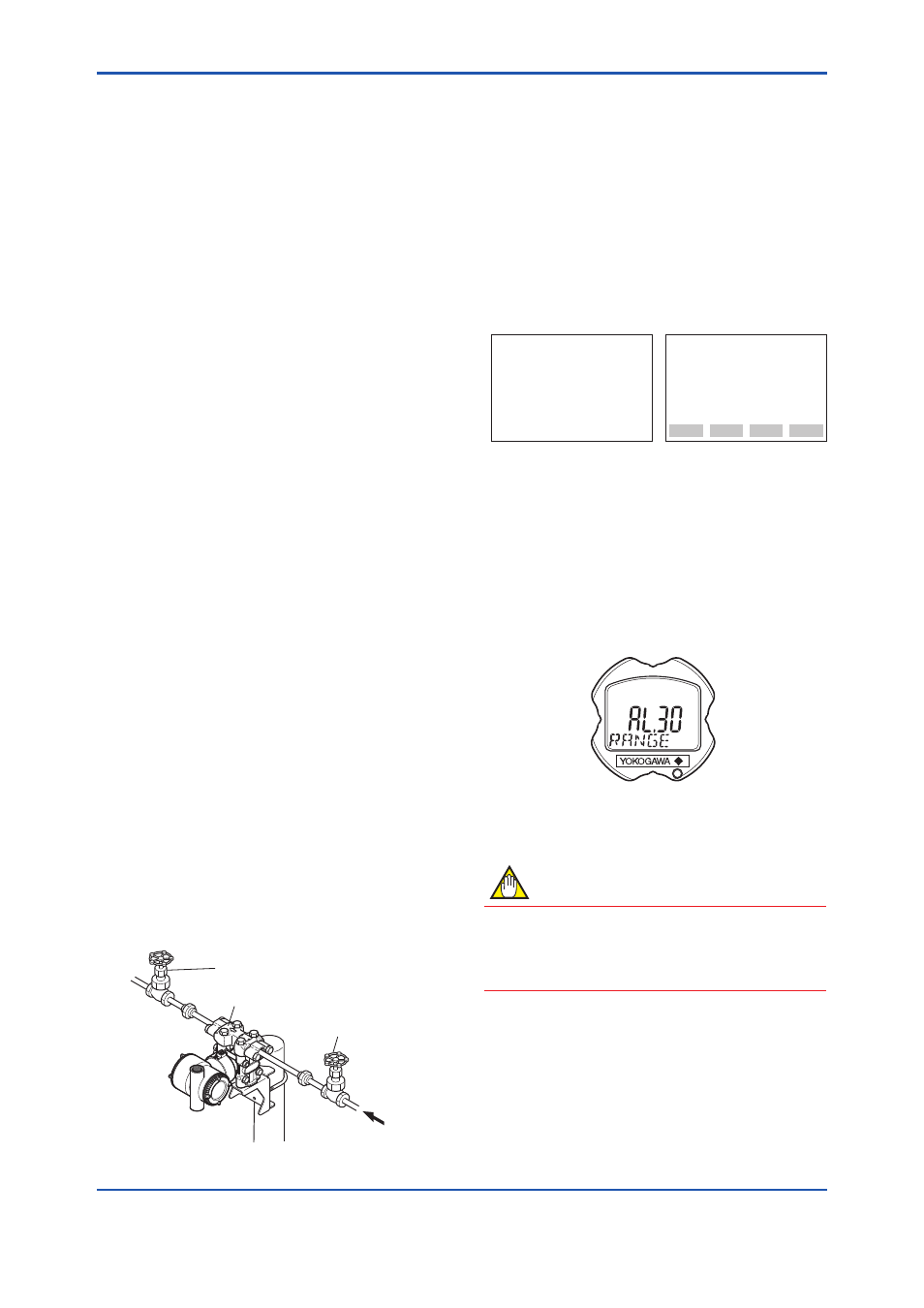
Using the integral indicator
• If the wiring system is faulty, the display stays
blank.
• If the transmitter is faulty, an error code is
displayed.
Self-diagnostic error on the integral indicator
(Faulty transmitter)
F0703.ai
Figure 7.3
Integral Indicator with Error Code
NOTE
If any of the above errors are indicated on
the display of the integral indicator or the
communicator, refer to subsection 8.5.3 for the
corrective action.