Important – Yokogawa EJX115A User Manual
Page 37
<7. Operation>
7-7
IM 01C25K01-01E
[Example]
Rerange LRV to 0 and URV to 3 MPa.
1) Connect the transmitter and apparatus as
shown in Figure 8.1 and warm it up for at least
five minutes.
2) Press the range-setting push-button.
The integral indicator then displays “LRV.SET.”
3) Apply a pressure of 0 kPa (atmospheric
pressure) to the transmitter.
(Note 1)
4) Turn the external zero-adjustment screw in the
desired direction. The integral indicator displays
the output signal in %.
(Note 2)
5) Adjust the output signal to 0% (1 V DC) by
rotating the external zero-adjustment screw.
Doing so completes the LRV setting.
6) Press the range-setting push-button. The
integral indicator then displays “URV.SET.”
7) Apply a pressure of 3 MPa to the
transmitter.
(Note 1)
8) Turn the external zero-adjustment screw in the
desired direction. The integral indicator displays
the output signal in %.
(Note 2)
9) Adjust the output signal to 100% (5 V DC) by
rotating the external zero-adjustment screw.
Doing so completes the URV setting.
10) Press the range-setting push-button. The
transmitter then switches back to the normal
operation mode with the measurement range of
0 to 3 MPa.
Note 1: Wait until the pressure inside the pressure-detector
section has stabilized before proceeding to the next step.
Note 2: If the pressure applied to the transmitter exceeds the
previous LRV (or URV), the integral indicator may display
error number “AL.30” (In this case, the output signal
percent and “AL.30” are displayed alternately every two
seconds). Although “AL.30” is displayed, you may proceed
to the next step. However, should any other error number
be displayed, take the appropriate measure in reference
to , “Errors and Countermeasures” in each communication
manual.
IMPORTANT
• Do not turn off the power to the transmitter
immediately after completion of the change
in the LRV and/or URV setting(s). Note
that powering off within thirty seconds after
setting will cause a return to the previous
settings.
• Changing LRV automatically changes URV
to the following value.
URV=previous URV+(new LRV–previous LRV)
• If the range-setting push-button and external
zero-adjustment screw are not touched
during a range-change operation, the
transmitter automatically switches back to
the normal operation mode.
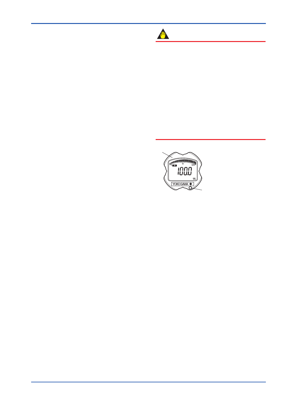
F0710.ai
Integral indicator
Range-setting switch
(Push-button)
Note 1: Use a thin bar which has a
blunt tip, e.g., a hexagonal
wrench, to press the
range-setting push-button.
Note 2: The push-button is located
in either lower right or
lower left portion of the
LCD indicator.
Figure 7.7
Range-setting Switch