Installation, 1 precautions, 2 mounting – Yokogawa EJX115A User Manual
Page 23: Installation -1, Precautions -1, Mounting -1, Important
<4. Installation>
4-1
IM 01C25K01-01E
4. Installation
4.1 Precautions
Before installing the transmitter, read the cautionary
notes in section 2.4, “Selecting the Installation
Location.” For additional information on the
ambient conditions allowed at the installation
location, refer to subsection 9.1 “Standard
Specifications.”
IMPORTANT
• When welding piping during construction,
take care not to allow welding currents to
flow through the transmitter.
• Do not step on this instrument after
installation.
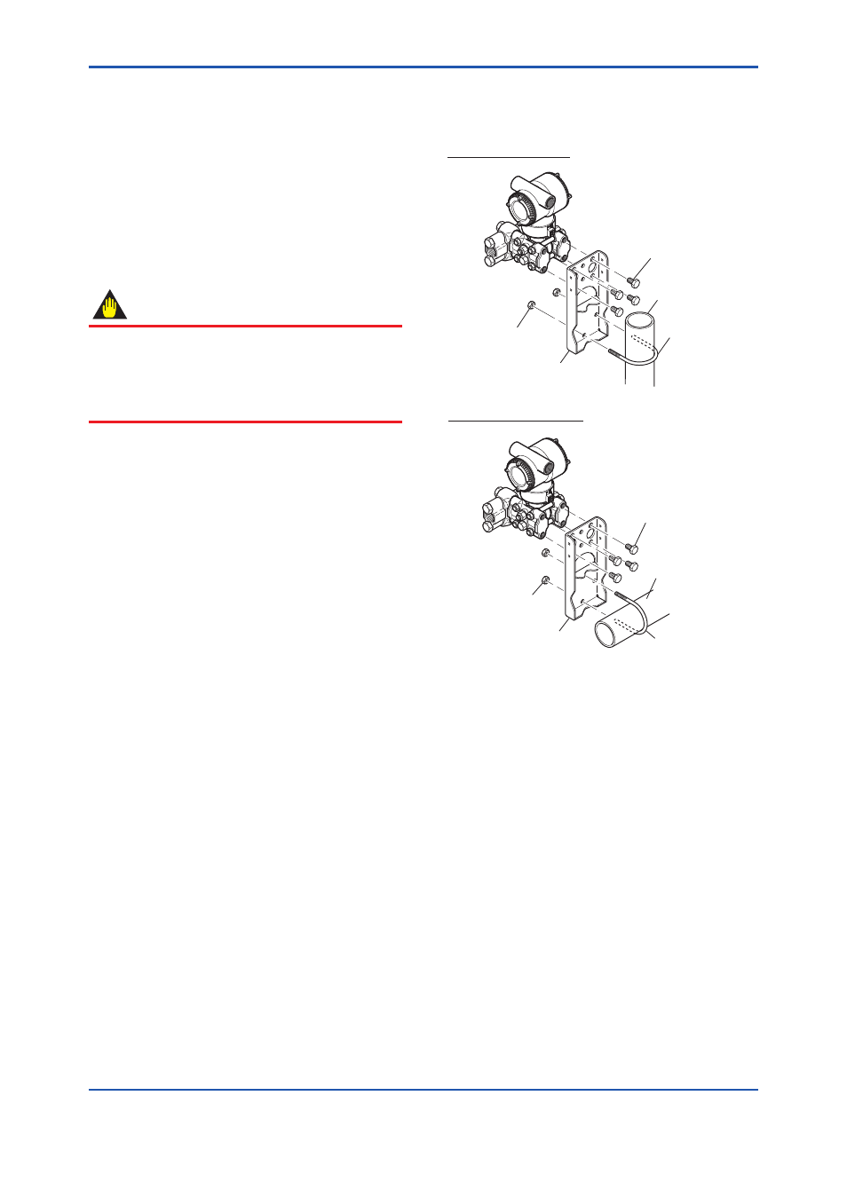
4.2 Mounting
The transmitter can be mounted on a nominal
50 mm (2-inch) pipe using the mounting
bracket supplied, as shown in figure 4.1 and
4.2 The transmitter can be mounted on either a
horizontal or a vertical pipe.
When mounting the bracket on the transmitter,
tighten the (four) bolts that hold the transmitter
with a torque of approximately 39 N·m {4kgf·m}.
The transmitter is shipped with the manifold set
up as per the order specifications.
For correct flow measurement, the flow path
must always be filled with fluid; otherwise,
measurement accuracy cannot be assured.
For the vertical impulse piping type, it is
recommended that the manifold be mounted
facing up for liquid flow measurement; facing
down for gas flow measurement, as shown in
Figure 4.2.
Figure 4.1 and 4.2 shows the mounting of the
transmitter for horizontal piping and vertical piping
with using the mounting bracket.
Horizontal pipe mounting
Vertical pipe mounting
Transmitter
mounting bolt
U-bolt nut
Mounting bracket
U-bolt nut
Mounting bracket
50 mm(2-inch) pipe
50 mm(2-inch) pipe
U-bolt
U-bolt
F0401.ai
Transmitter
mounting bolt
Figure 4.1
Transmitter Mounting
(Horizontal Impulse Piping Type)