Component names, Component names -1 – Yokogawa EJX115A User Manual
Page 22
<3. Component Names>
3-1
IM 01C25K01-01E
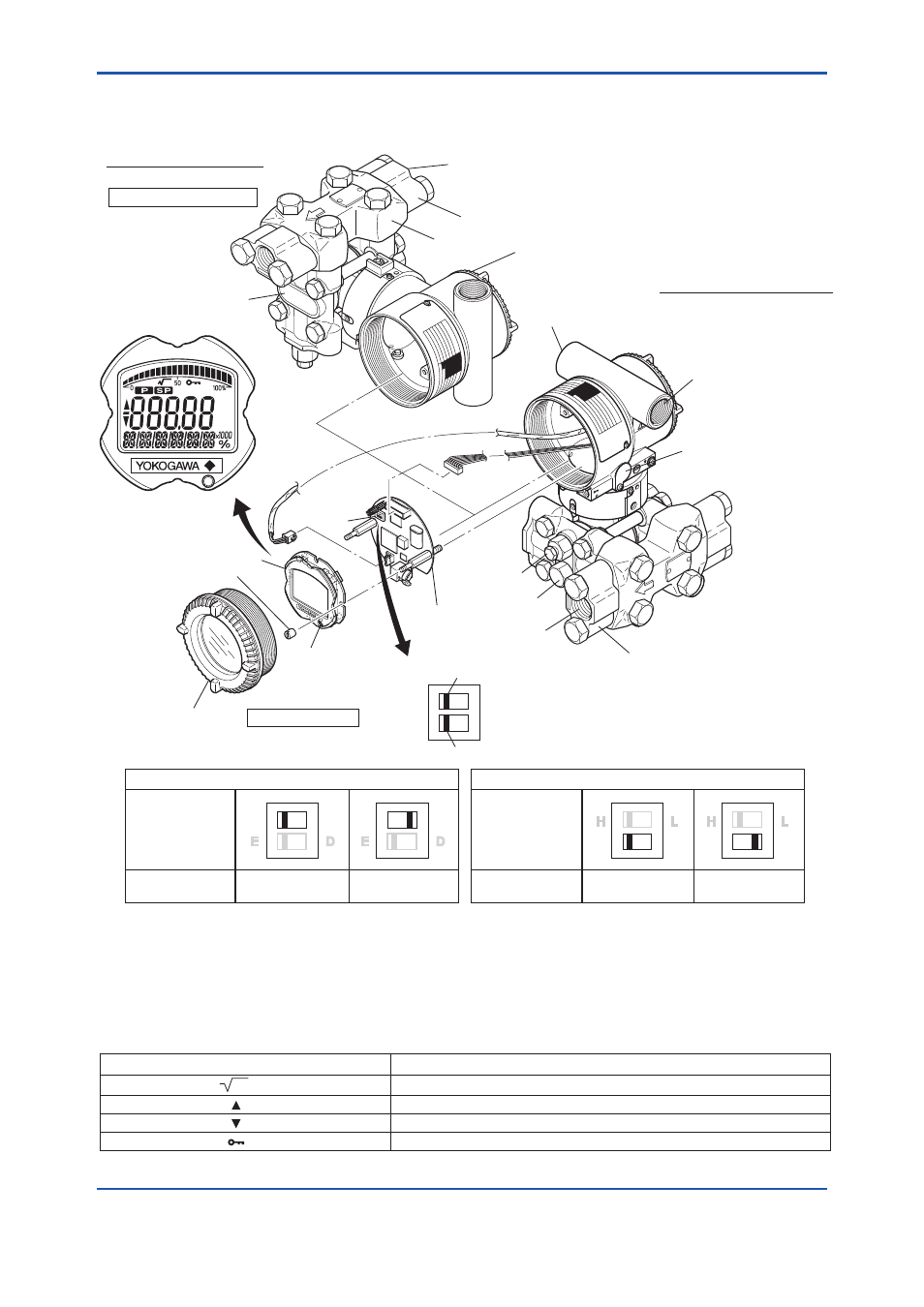
3. Component Names
HIGH
LOW
Burnout Direction
Switch Position
Burnout direction switch
Write protection switch
BO H
L
WR E
D
H
L
H
L
Burnout direction switch (BO)
Burnout Direction
F0301.ai
Write Protection
Switch Position
H
L
E
D
H
L
E
D
Write Protection
Hardware write protection switch (WR)
YES
(Write disabled)
NO
(Write enabled)
Vertical impulse piping type
Pressure-detector section
Cover flange
Terminal box cover
Horizontal impulse piping type
External indicator
conduit connection
(Note 1)
Vent plug
Drain plug
Transmitter section
Integral
indicator
(Note 1)
Mounting screw
Range-setting
switch
(Note 1)
(See section 7.6)
Amplifier Cover
CPU assembly
Zero-
adjustment
screw
Conduit
connection
Process connector
Process connector
Process connection
Process
connection
(Note 2)
Manifold
Slide switch
Note 1: See subsection 9.2, “Model and Suffix Codes,” for details.
Note 2: Applicable for BRAIN/HART communication type. Set the switches as shown in the figure above to set the burn-out direction
and write protection. The Burnout switch is set to the H side for delivery (unless option code /C1 or /C2 is specified in the order),
and the hardware write protection switch is set to E side. The setting of the switches can be confirmed via communication. An
external zero adjustment screw can only be disabled by communication. To disable the screw, set a parameter before activating
the hardware write protect function. See each communication manual.
Figure 3.1
Component Names
Table 3.1
Display Symbol
Display Symbol
Meaning of Display Symbol
Display mode is ‘square root’. (Display is not lit when ‘linear’ mode.)
The output signal being zero-adjusted is increasing.
The output signal being zero-adjusted is decreasing.
F0302.ai
Write protect function is enabled.