2 replacing the cpu board assembly, 3 replacing the process connector gaskets, 4 cleaning manifold assembly and replacing orifice – Yokogawa EJX115A User Manual
Page 41: Replacing the cpu board assembly -4, Replacing the process connector gaskets -4
<8. Maintenance>
8-4
IM 01C25K01-01E
8.4.2 Replacing the CPU Board Assembly
This subsection describes the procedure for
replacing the CPU assembly. (See figure 8.3)
■ Removing the CPU Assembly
1) Remove the cover. If an integral indicator is
mounted, refer to subsection 8.4.1 and remove
the indicator.
2) Turn the zero-adjustment screw to the position
(where the screw head slot is horizontal) as
shown in figure 8.3.
3) Disconnect the output terminal cable (cable
with brown connector at the end). When doing
this, lightly press the side of the CPU assembly
connector and pull the cable connector to
disengage.
4) Use a socket driver (width across flats, 5.5mm)
to loosen the two bosses.
5) Carefully pull the CPU assembly straight
forward to remove it.
6) Disconnect the flat cable (cable with white
connector at the end) that connects the CPU
assembly and the capsule.
NOTE
Be careful not to apply excessive force to the
CPU assembly when removing it.
■ Mounting the CPU Assembly
1) Connect the flat cable (with white connector)
between the CPU assembly and the capsule.
2) Connect the output terminal cable (with brown
connector).
NOTE
Make certain that the cables do not get pinched
between the case and the edge of the CPU
assembly.
3) Align and engage the zero-adjustment screw
pin with the groove on the bracket on the CPU
assembly. Then insert the CPU board assembly
straight onto the post in the amplifier case.
4) Tighten the two bosses. If the transmitter is
equipped with an integral indicator, refer to
subsection 8.4.1 to mount the indicator.
NOTE
Confirm that the zero-adjustment screw pin is
placed properly in the groove on the bracket prior
to tightening the two bosses. If it is not, the zero-
adjustment mechanism will be damaged.
5) Replace the cover.
8.4.3 Replacing the Process Connector
Gaskets
This subsection describes process connector
gasket replacement. (See Figure 8.4.)
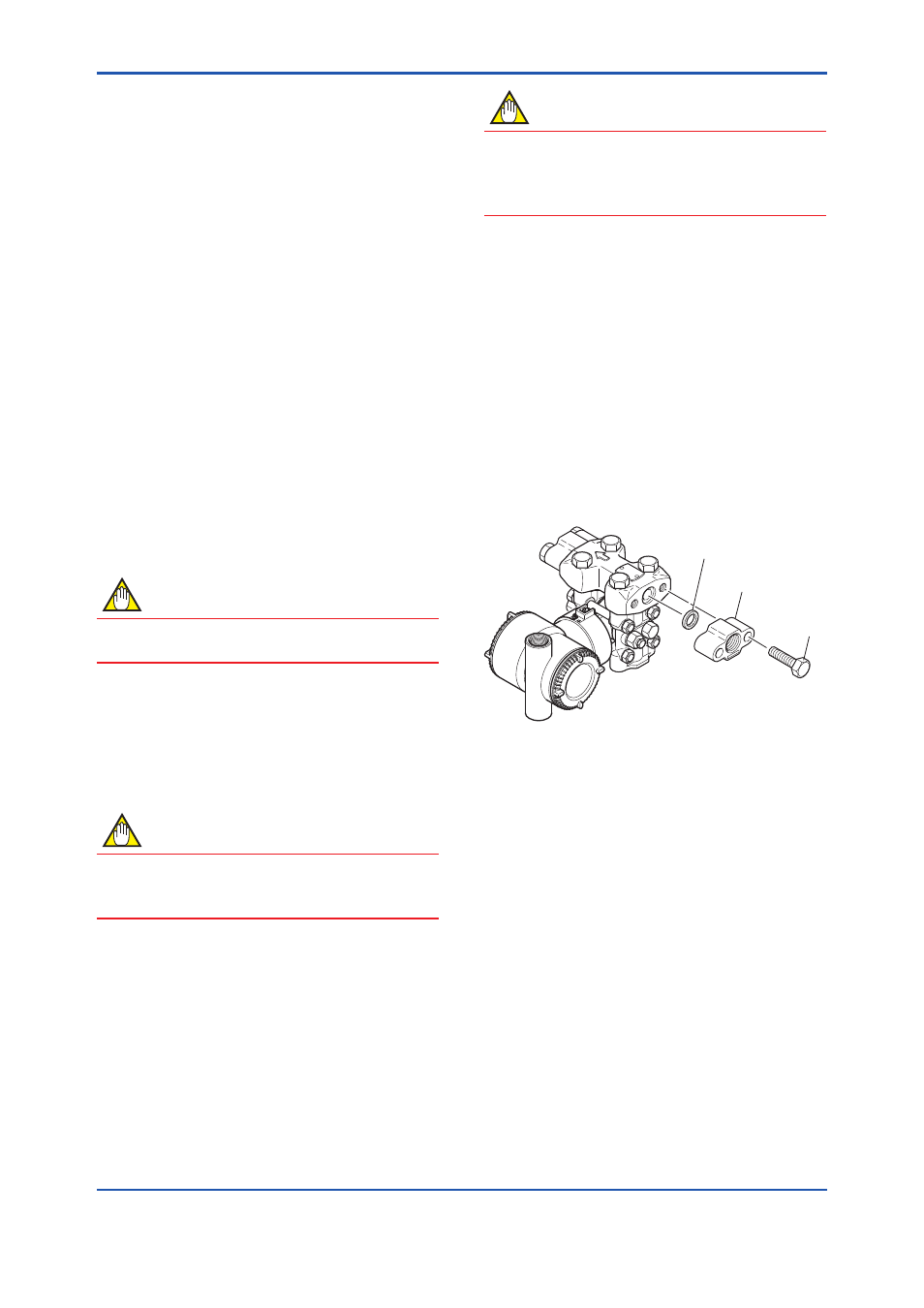
(a) Loosen the two bolts, and remove the process
connectors.
(b) Replace the process connector gaskets.
(c) Remount the process connectors. Tighten the
bolts securely and uniformly with a torque of 39
to 49 N·m {4 to 5 kgf·m}, and verify that there
are no pressure leaks.
F0804.ai
Process connector
Process connector gasket
Bolt
Figure 8.4
Removing and Mounting the Process
Connector
8.4.4 Cleaning Manifold Assembly and
Replacing Orifice
This subsection describes the procedures for
cleaning the manifold assembly and replacing the
orifice to change flow rate. (See Figure 8.5.)
■ Removing the Manifold Assembly
1) Remove the process connector as shown in
Subsection 9.4.3.
2) Remove the four bolts that connect the cover
flange with the manifold.
3) Remove the spacer, orifice, and orifice gasket
from inside the manifold.
4) Clean the manifold, spacer, and orifice, or
replace them as necessary.