2 zero point adjustment, 3 starting operation, Zero point adjustment -2 – Yokogawa EJX115A User Manual
Page 32: Starting operation -2, Important
<7. Operation>
7-2
IM 01C25K01-01E
Verify and Change Transmitter
Parameter Setting and Values
The parameters related to the following items are
set at factory as specified in order.
• Calibration range
• Integral indicator display
• Output mode
• Software damping (optional)
Other parameters like following are shipped with the
default setting.
• Low-cut
• Process alarm setting
• Static pressure range
• Signal characterizer
• Write protection
To confirm or change the values, see IM 01C25T01-
06EN or 01C25T03-01E.
7.2 Zero Point Adjustment
After completing preparations for operating the
transmitter, adjust the zero point.
Zero point adjustment can be done by turning the
transmitter’s zero-adjustment screw or by using
the communicator. This section describes the
procedure for the zero-adjustment screw. For the
communicator procedure, see the communication
manual.
IMPORTANT
Do not turn off the power to the transmitter
immediately after performing a zero point
adjustment. Powering off within 30 seconds of
performing this procedure will return the zero
point to its previous setting.
NOTE
Before performing this adjustment, make sure
that the external zero adjustment function has
NOT been disabled by a parameter setting.
To check the output signal, use a digital multimeter,
calibrator, or communicator.
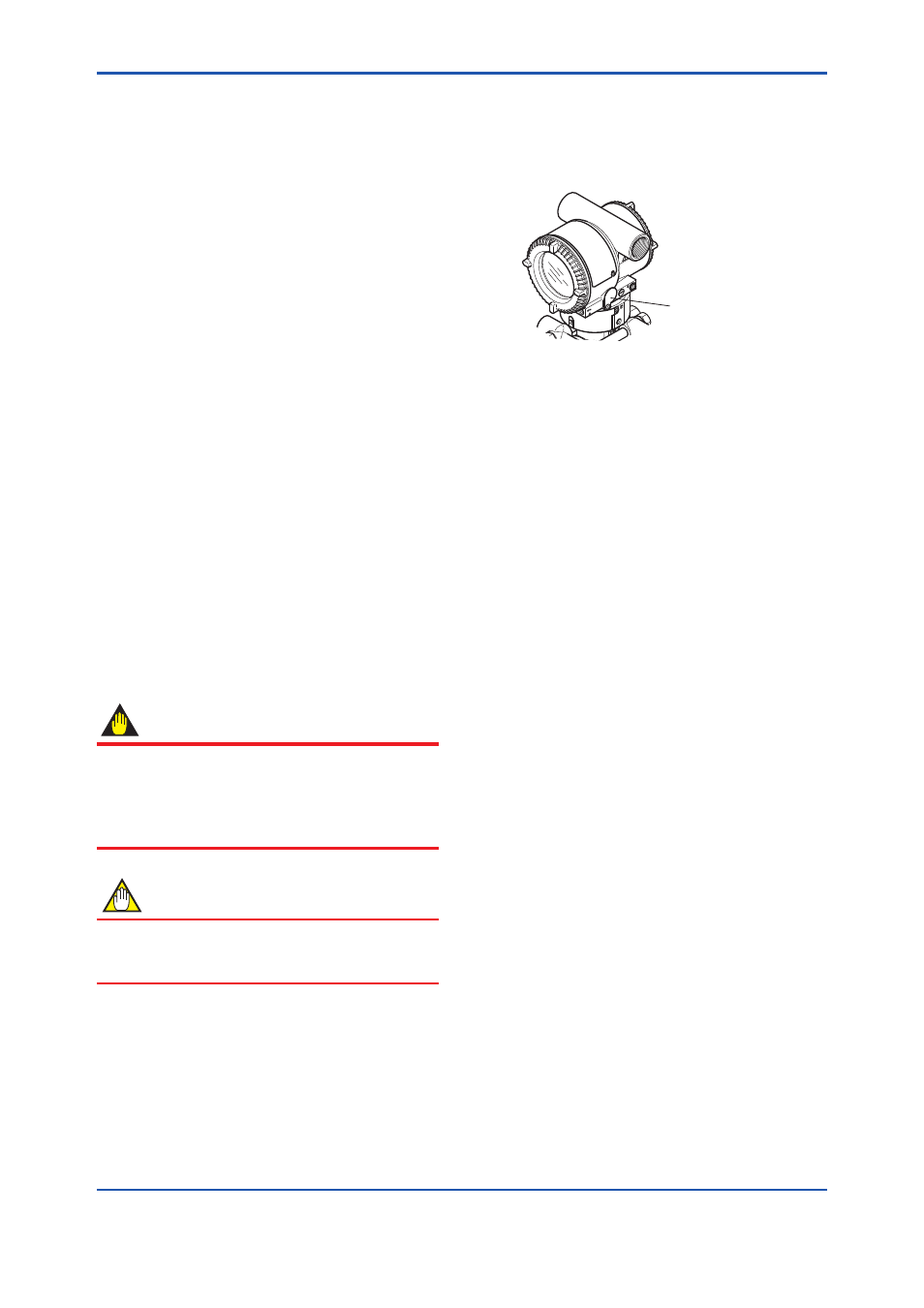
Adjusting Zero Point for Differential
Pressure Transmitters
Before adjusting zero point, make sure that the
equalizing valve is open.
Zero-adjustment
screw cover
F0704.ai
Figure 7.4
External Zero Adjustment Screw
The zero-adjustment screw is located inside the
cover.
Use a slotted screwdriver to turn the zero-
adjustment screw. Equalize the transmitter, then
turn the screw clockwise to increase the output or
counterclockwise to decrease the output. The zero
point adjustment can be made with a resolution
of 0.01% of the setting range. The degree of zero
adjustments varies with the screw turning speed;
turn the screw slowly to make a fine adjustment,
quickly to make a rough adjustment.
7.3 Starting Operation
After completing the zero point adjustment, follow
the procedure below to start operation.
1) Open the stop valve on the upstream side.
2) Gradually open the stop valve on the
downstream side. This places the transmitter in
an operational condition.
3) Confirm the operating status. If the output
signal exhibits wide fluctuations (hunting) due
to periodic variation in the process pressure,
use BT200 to dampen the transmitter output
signal. Confirm the hunting using a receiving
instrument or the integral indicator, and set the
optimum damping time constant.
4) After confirming the operating status, perform
the following.