5 cleaning and replacing the capsule assembly, Cleaning and replacing the capsule assembly -5, Important – Yokogawa EJX115A User Manual
Page 42: Caution
<8. Maintenance>
8-5
IM 01C25K01-01E
IMPORTANT
Exercise care as follows when cleaning the
manifold assembly.
• Handle the manifold assembly with care, and
be careful not to damage the inner part of the
manifold, spacer, and orifice. Be especially
careful not to damage or distort the orifice
edge (orifice bore).
• Do not use a chlorinated or acidic solution for
cleaning.
• Rinse thoroughly with clean water after
cleaning.
■ Reassembling the Manifold Assembly
1) Reassemble the orifice gasket, orifice, and
spacer into the manifold in that order.
When reassembling, refer to Figure 8.5 to
ensure that they are placed in the correct
direction.
Replace the orifice gasket with a new gasket.
2) Mount the process connector as shown in
Subsection 9.4.3.
3) Mount the manifold on the cover flange with the
four bolts. Tighten the four bolts uniformly to a
torque of 39 to 49 N·m {4 to 5 kgf·m}.
Replace the manifold gaskets with new
gaskets.
4) After completing reassembly, a leak test
must be performed to verify that there are no
pressure leaks.
NOTE
Exercise care as follows when reassembling the
manifold assembly. (See Figure 8.5.)
• Be careful not to reassemble the orifice in
the wrong direction. Note that the spacer is
configured so that it cannot be placed in the
reverse direction.
• When mounting the manifold on the cover
flange, confirm the indication “flow direction”
shown on the manifold surface and the high
and low pressure sides of the pressure-
detector section.
Mount the manifold so that the upstream
side of process fluid flow is located at the
high pressure side of the pressure-detector
section.
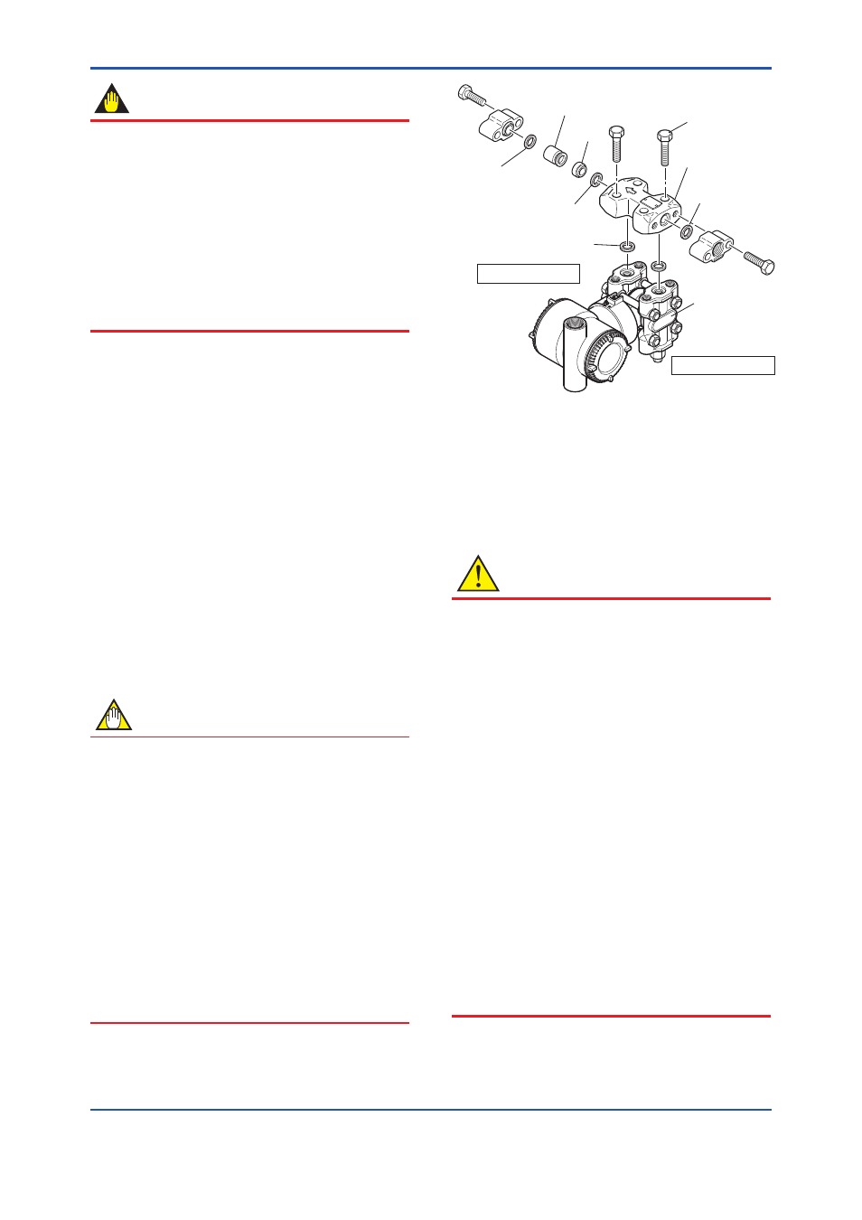
F0805.ai
Process connector
gasket
Process connector
gasket
Spacer
Orifice
Bolt
Orifice gasket
Manifold gasket
Cover flange
Manifold
Low pressure side
High pressure side
Figure 8.5
Manifold Assembly
8.4.5 Cleaning and Replacing the Capsule
Assembly
This subsection describes the procedures for
cleaning and replacing the capsule assembly. (See
figure 8.6.)
CAUTION
Cautions for Flameproof Type Transmitters
Users are prohibited by law from modifying the
construction of a flameproof type transmitter. If
you wish to replace the capsule assembly with
one of a different measurement range, contact
Yokogawa.
The user is permitted, however, to replace a
capsule assembly with another of the same
measurement range. When doing so, be sure to
observe the following.
• The replacement capsule assembly must
have the same part number as the one being
replaced.
• The section connecting the transmitter and
capsule assembly is a critical element in
preservation of flameproof performance, and
must be checked to verify that it is free of
dents, scratches, and other defects.
• After completing maintenance, be sure to
securely tighten the setscrews that fasten
the transmitter section and pressure-detector
section together.