2 process piping connection examples, Process piping connection examples -2 – Yokogawa EJX115A User Manual
Page 27
<5. Installing Impulse Piping>
5-2
IM 01C25K01-01E
(3) Preventing Freezing
If there is any risk that the process fluid in the
transmitter pressure-sensing assembly could freeze
or solidify, use a steam jacket or heater to maintain
the temperature of the fluid.
F0502.ai
Manifold
Figure 5.2
Manifold Location at the Downside (for
Gas Flow Measurement)
F0503.ai
Manifold
Figure 5.3
Manifold Location at the Upside (for
Liquid Flow Measurement)
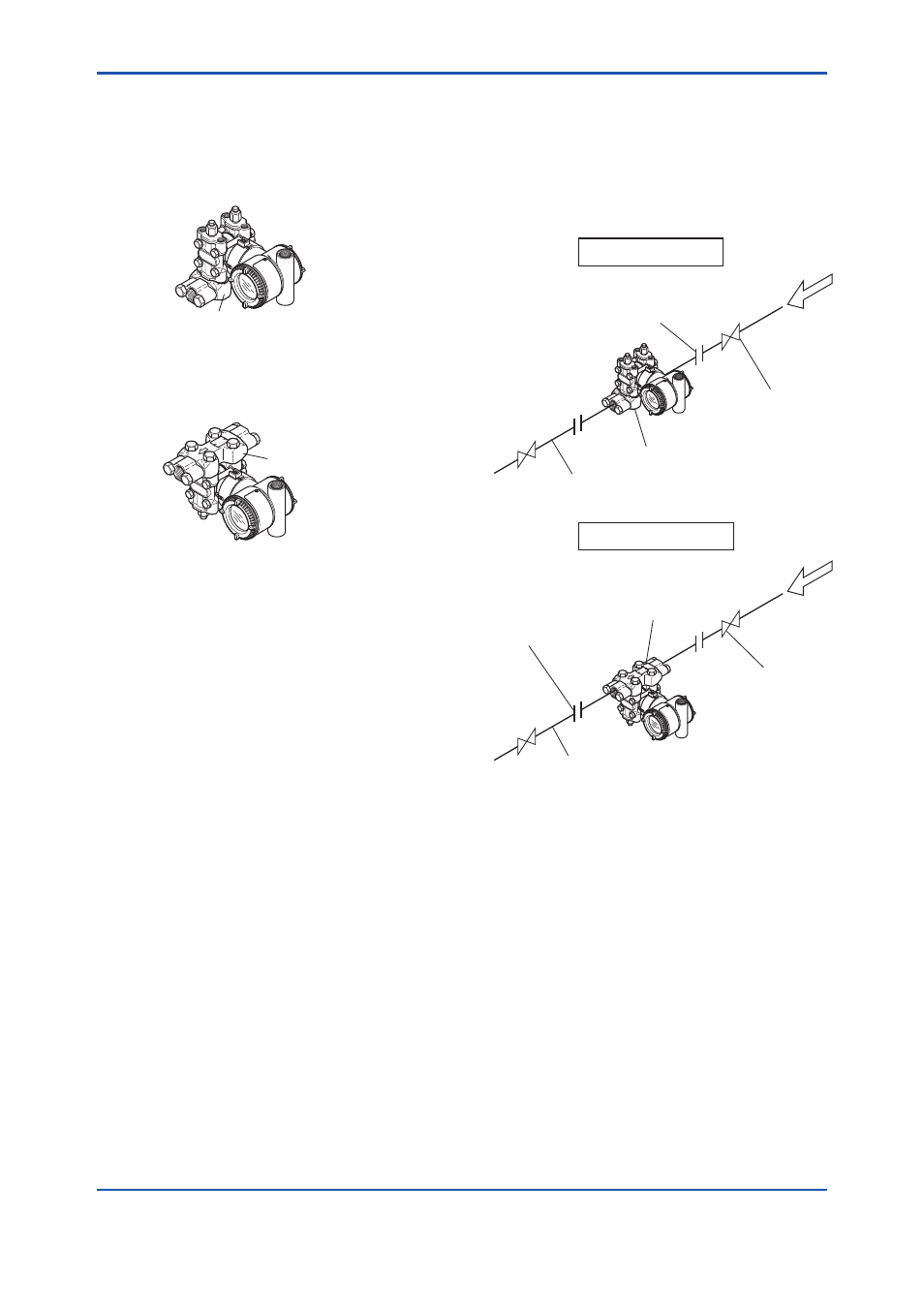
5.2 Process Piping Connection
Examples
Figure 5.4 shows examples of typical process
piping connections. Before connecting the
transmitter to the process, study the transmitter
installation location, the process piping layout,
and the characteristics of the process fluid
(corrosiveness, toxicity, flammability, etc.), in order
to make appropriate changes and additions to the
connection configurations.
Note the following points when referring to these
piping examples.
• The high pressure connecting port on the
transmitter is shown on the right (as viewed
from the front).
• The transmitter process piping connection is
shown for a vertical impulse piping connection
configuration in which the direction of process
flow is from right to left.
• The process piping material used must
be compatible with the process pressure,
temperature, and other conditions.
• A variety of process piping-mounted stop
valves are available according to the type
of connection (flanged, screwed, welded),
construction (globe, gate, or ball valve),
temperature and pressure. Select the type of
valve most appropriate for the application.
F0504.ai
Gas flow measurement
Liquid flow measurement
Union or flange
Union or flange
Stop valve
Stop valve
Manifold
Manifold
Process piping
Process piping
Figure 5.4
Process Piping Connection Examples