5 unit for displayed temperature, 6 sensor trim, Unit for displayed temperature -18 – Yokogawa EJA440E User Manual
Page 31: Sensor trim -18
<3. Parameter Setting>
3-18
IM 01C25T01-06EN
Setting by EJX HART 5 DTM based on
FDT1.2
User can input the desired unit at
Engr Unit.
• Procedure to call up the display
EJX HART 5 DTM
based on FDT1.2
Configuration →Local Display →
→ Engr Unit
Set the engineering unit
→ Engr LRV
Lower range value
→ Engr URV
Upper range value
→ Engr exp
Exponents for user scale display
→ Engr point
Decimal point position for user
scale display
Available characters and symbols for
Engr Unit are
the same as for
Modify Engr Unit shown above.
3.3.5 Unit for Displayed Temperature
When the instrument is shipped, the temperature
units are set to “deg C” (Centigrade). Follow the
procedure below to change this setting.
When this parameter is set, it also changes the
temperature unit for
Snsr temp at Process
variables and Amp temp at Temp sensor.
• Procedure to call up the display
DD and DTM
(excluding EJX_
HART 5[1.2])
[Root Menu] → Detailed setup →
Sensors → Temp sensor →
EJX_HART 5[1.2]
DTM
Configuration → Process Input →
→ Temp Unit
Select the temperature unit
(deg C, deg F, Kelvin(K))
3.3.6 Sensor Trim
The transmitter is factory characterized. Factory
characterization is the process of comparing a
known pressure input with the output of each
transmitter sensor module over the entire pressure
and temperature operating range. During the
characterization process, this comparison
information is stored in the transmitter EEPROM. In
operation, the transmitter uses this factory-stored
curve to produce a process variable output (PV), in
engineering units, dependent on the pressure input.
The sensor trim procedure allows you to adjust
for local conditions, changing how the transmitter
calculates process variables. There are two ways
to trim the sensor: a zero trim and a full sensor trim.
A zero trim is a one-point adjustment typically used
to compensate for mounting position effects or
zero shifts caused by static pressure. A full sensor
trim is a two-point process, in which two accurate
end-point pressures are applied (equal to or greater
than the range values), and all output is linearized
between them.
(1) Zero Trim
a. Zeroing—Pres Zero trim
Pres Zero trim carries out the zero adjustment and
automatically sets the applied “0” input values to the
output value of “0”, keeping the span constant. Use
this setting when the LRV is known to be 0 mmH
2
O.
• Procedure to call up the display
DD and DTM
(excluding EJX_
HART 5[1.2])
[Root Menu] → Diag/Service
→ Calibration → Pres Sensor
trim →
EJX_HART 5[1.2]
DTM
Calibration →
→ Pres Zero trim
Adjust the lower point
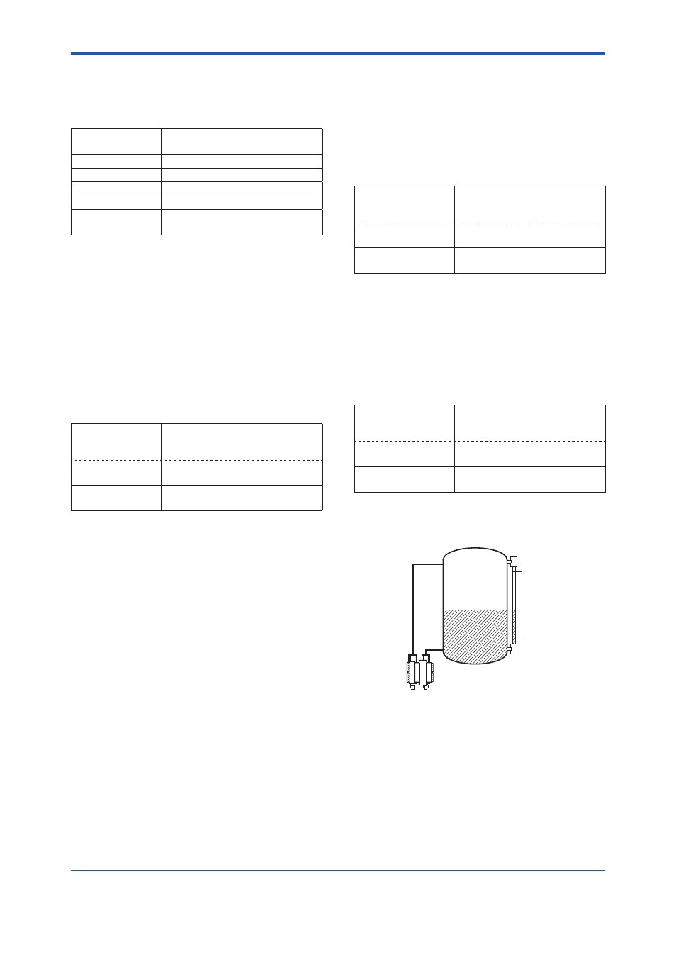
b. Level Adjustment—Auto, lower Pt
This zero adjustment calibrates the transmitter
output corresponding to the actual tank level. To
perform this adjustment, first use a glass gauge
or the like to determine the actual tank level, then
enter the correct data as shown below.
• Procedure to call up the display
DD and DTM
(excluding EJX_
HART 5[1.2])
[Root Menu] → Diag/Service →
Calibration → Pres Sensor trim
→ Pres trim →
EJX_HART 5[1.2]
DTM
Calibration → Pres trim →
→ Auto, Lower Pt
Auto trim for 0% point
F0306.ai
25.00 kPa
0.00 kPa
Actual level
13.50 kPa
DPharp span: 0 to 25.00 kPa
Actual level: 13.50 kPa
Transmitter output: 13.83 kPa
DPharp
c. Using External Zero-adjustment Screw
This method permits zero adjustment without
the HART configuration tool. Use a slotted
screwdriver to turn the zero-adjustment screw.
See the hardware manual for details.
Note that the parameter of
Ext SW must be
“Enabled” to perform this adjustment. See
section 3.3.8 for the setting procedure.