Proface APL3000B - Node Box PC User Manual
Page 59
PS-3650A / PS-3651A Reference Manual
3-8
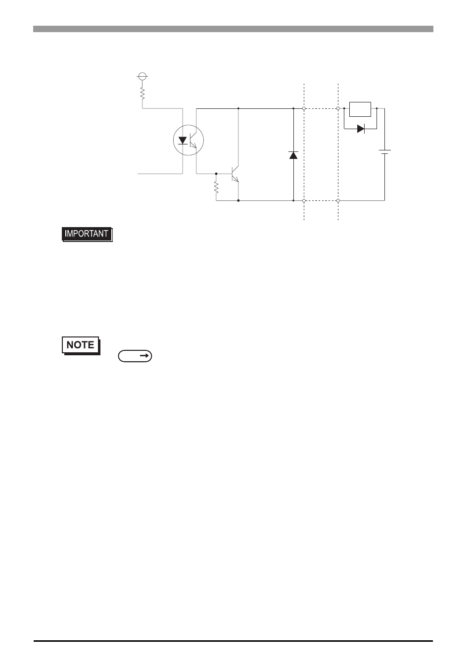
• Be sure to operate the unit within its maximum load current. If the maximum load
current exceeds this range, a malfunction or PS-A damage may occur.
• Design your electrical system by adding the load current and voltage values to the
terminal voltage. If load current value used is large, the voltage drop of 1.5V or less
will occur between the terminals.
• When connecting an induction load, be sure to connect the above drawing’s
protection diode (*1).
•
For connection pin location details,
+5V
R
PC357
4.7kΩ
SSTA06
Cable
*
1
DC12V
to
24V
DOUT0(-) # 7
DOUT1(-) # 8
DOUT0(+) pin # 2
DOUT1(+) pin # 3
( Interface Circuit )
Load
SEE
PS-3650A/PS-3651A Series Hardware Manual 2 Specifications