Proface APL3000B - Node Box PC User Manual
Page 57
PS-3650A / PS-3651A Reference Manual
3-6
External Input Signals
The PS-A’s RAS interface connector uses the following input signals.
•
General-Purpose Input (DIN 2 bits)
This standard digital input is used for error/alert detection in external devices. The input signal uses two bits.
The System Monitor property of the control panel or the API-DLL can be used to enable or disable this
feature, as well as designate what type of processing is to be performed once a signal is received. (Only
the “ON” state of the DIN circuit is detected. The “OFF” state of the DIN circuit cannot be monitored.)
•
Remote Reset Input
This is the reset signal sent from an external device to the PS-A. When this signal is enabled, a forced
reset of the PS-A is performed.
The System Monitor property of the control panel or the API-DLL can be used to enable or disable this
feature.
•
To enable Remote Reset Input, make sure to check the [Enable] in the Remote reset tab of
System Monitor Property. For Remote reset of System Monitor Property, refer to the following.
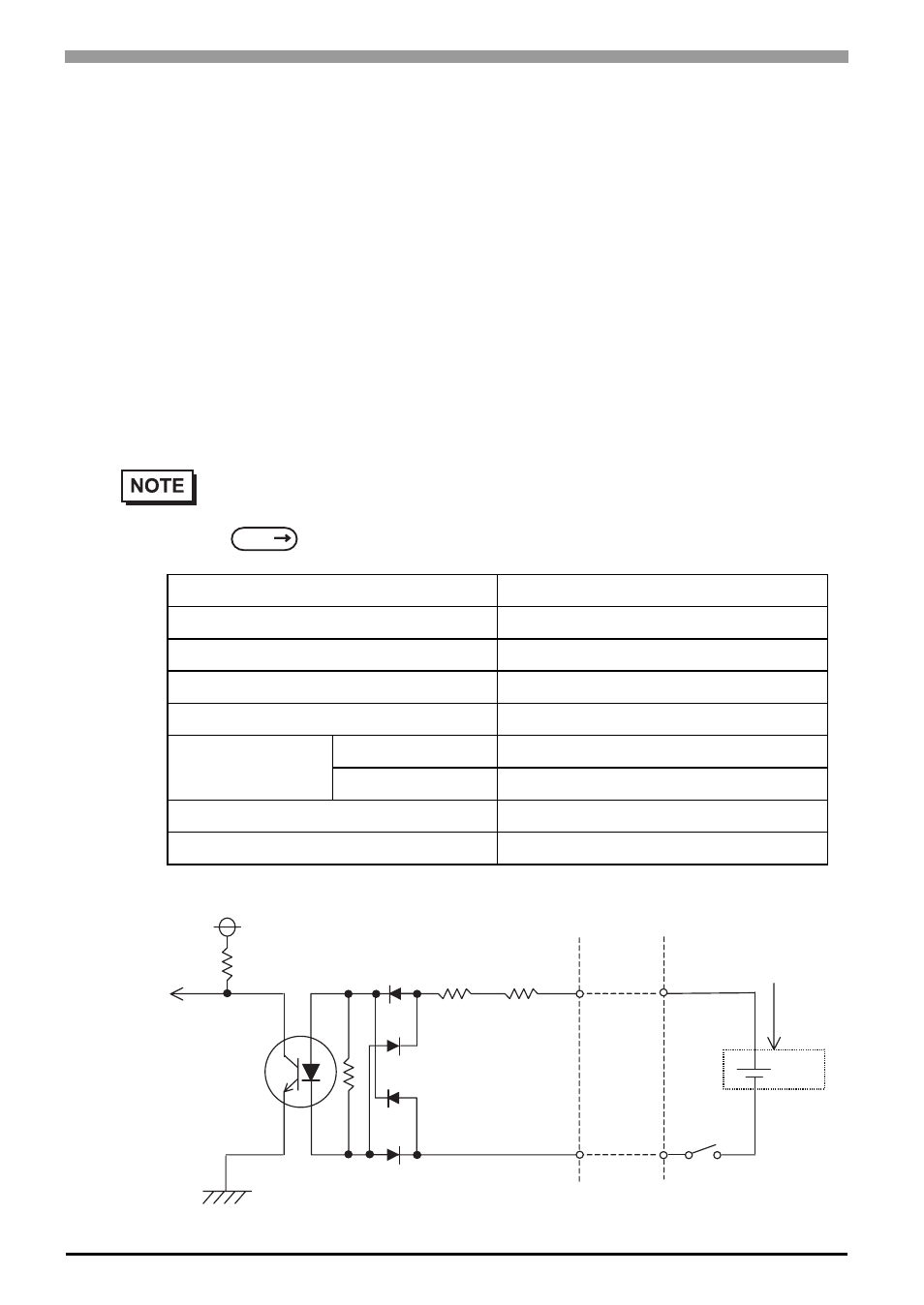
Input Voltage
DC12V to 24V
Input Method
Sink / Source Input
Input Current
10mA ( DC24V )
Input Resistance
3.6k
Ω
Input Points
2 points (common with external reset input)
Operation Range
ON voltage
DC10V or more
OFF voltage
DC3V or less
Isolation Method
Photocoupler Isolation
Dielectric Strength Voltage
500V or more
SEE
(Interface Circuit)
+5V
1.8k
Ω
1/10W
1.8k
Ω
1/10W
R
R
PC357
No polarity - for Sink /
Source input
switch or other
switching device
Cable
DC12V
to 24V
DINCOM pin # 9
DIN0(+) pin
#
4
DIN1(+) pin
#
5