4 cabinet and rack installation, Figure 3-17: arm mounting retention screw holes – IEI Integration AFL-F08A v1.01 User Manual
Page 44
AFL-F08A Panel PC
Page 32
Step 3:
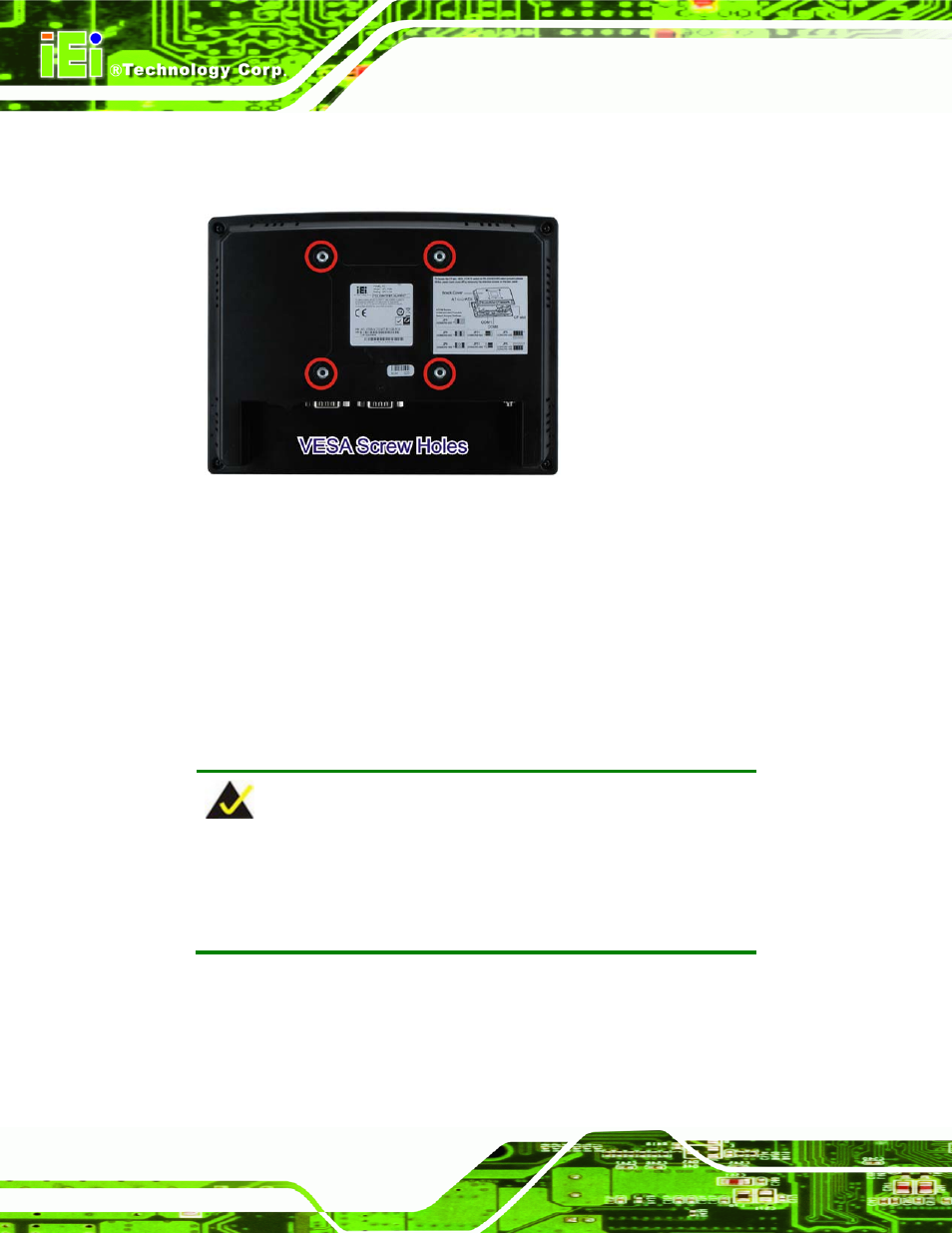
Align the retention screw holes on the mounting arm interface with those in the
flat panel PC.
Figure 3-17: Arm Mounting Retention Screw Holes
Step 4:
Secure the system to the interface pad by inserting four retention screws
through the bottom of the mounting arm interface pad and into the flat panel PC.
Step 0:
3.8.4 Cabinet and Rack Installation
The AFL-F08A can be installed into a cabinet or rack. The installation procedures are
similar to the panel mounting installation. To do this, please follow the steps below:
NOTE:
When purchasing the cabinet/rack installation bracket, make sure it is
compatible with both the AFL-F08A and the rack/cabinet into which the
AFL-F08A is installed.
Step 1:
Slide the rear chassis of the AFL-F08A through the rack/cabinet bracket until the
aluminum frame is flush against the front of the bracket (Figure 3-18).
- UPC-V312-D525 v1.02 (176 pages)
- UPC-V312-D525 v1.10 (175 pages)
- UPC-12A_GM45 v1.00 (147 pages)
- UPC-12A_GM45 v2.00 (144 pages)
- UPC-12A_GM45 v2.10 (145 pages)
- UPC-V315-NM70 (148 pages)
- UPC-V315-Screw Driver (1 page)
- UPC-V315-QM77 (148 pages)
- S12ASR v1.12 (110 pages)
- S12ASR v3.00 (118 pages)
- PPC-5xxx-9455 v1.00 (198 pages)
- PPC-5xxx-9455 v1.10 (198 pages)
- PPC-WIDS-51xxA-G41 (152 pages)
- PPC-51xxA-H61 (193 pages)
- PPC-5152-D525 v1.02 (183 pages)
- PPC-5152-D525 v2.10 (185 pages)
- PPC-37xxA-N26 v1.00 (203 pages)
- PPC-37xxA-N26 v1.10 (200 pages)
- PPC-37xx-N270 v1.01 (165 pages)
- PPC-37xx-N270 v2.00 (155 pages)
- PPC-37xx-N270 v2.11 (155 pages)
- PPC-37xx-N270 v2.20 (162 pages)
- ACT-457A (67 pages)
- AFL-4 series-N270 v1.05 (165 pages)
- AFL-4 series-N270 v2.10 (166 pages)
- AFL-4 series-N270 v2.11 (168 pages)
- AFL-4 series-N270 v2.20 (168 pages)
- AFL-W19A_W19B_17D_W15A-GM45 v2.10 (138 pages)
- AFL-W19A_W19B_17D_W15A-GM45 v1.06 (138 pages)
- AFL-W19A_W19B_17D_W15A-GM45 v2.20 (151 pages)
- AFL-W15A_17D-GM45 v3.00 (148 pages)
- AFL-15i-HM55 v1.01 (139 pages)
- AFL-19i-HM55 v2.00 (140 pages)
- AFL-15i-HM55 v1.20 (143 pages)
- AFL-W19A_W19B_17D_W15A-N270 v1.06 (125 pages)
- AFL-W19A_W19B_17D_W15A-N270 v2.20 (124 pages)
- AFL-W19A_17D_W15A-N270 v3.00 (126 pages)
- AFL-15A_15AE-N270_UMN_v1.01.pdf (158 pages)
- AFL-15A-N270 v1.03 (159 pages)
- AFL-15A-N270 v2.10 (159 pages)
- AFL-15A-N270 v2.20 (158 pages)
- AFL-xxA-N26 (152 pages)
- AFL-xxA-N270-Series v1.03 (171 pages)
- AFL-xxA-N270-Series v2.00 (171 pages)
- AFL-xxA-N270-Series v2.11 (170 pages)