2 clear cmos jumper, Figure 4-24: at/atx power mode jumper location, Table 4-29: at/atx power mode jumper settings – IEI Integration ECN-360A-HM65 User Manual
Page 63
ECN-360A-HM65 Em b e d d e d S ys te m
P a g e 50
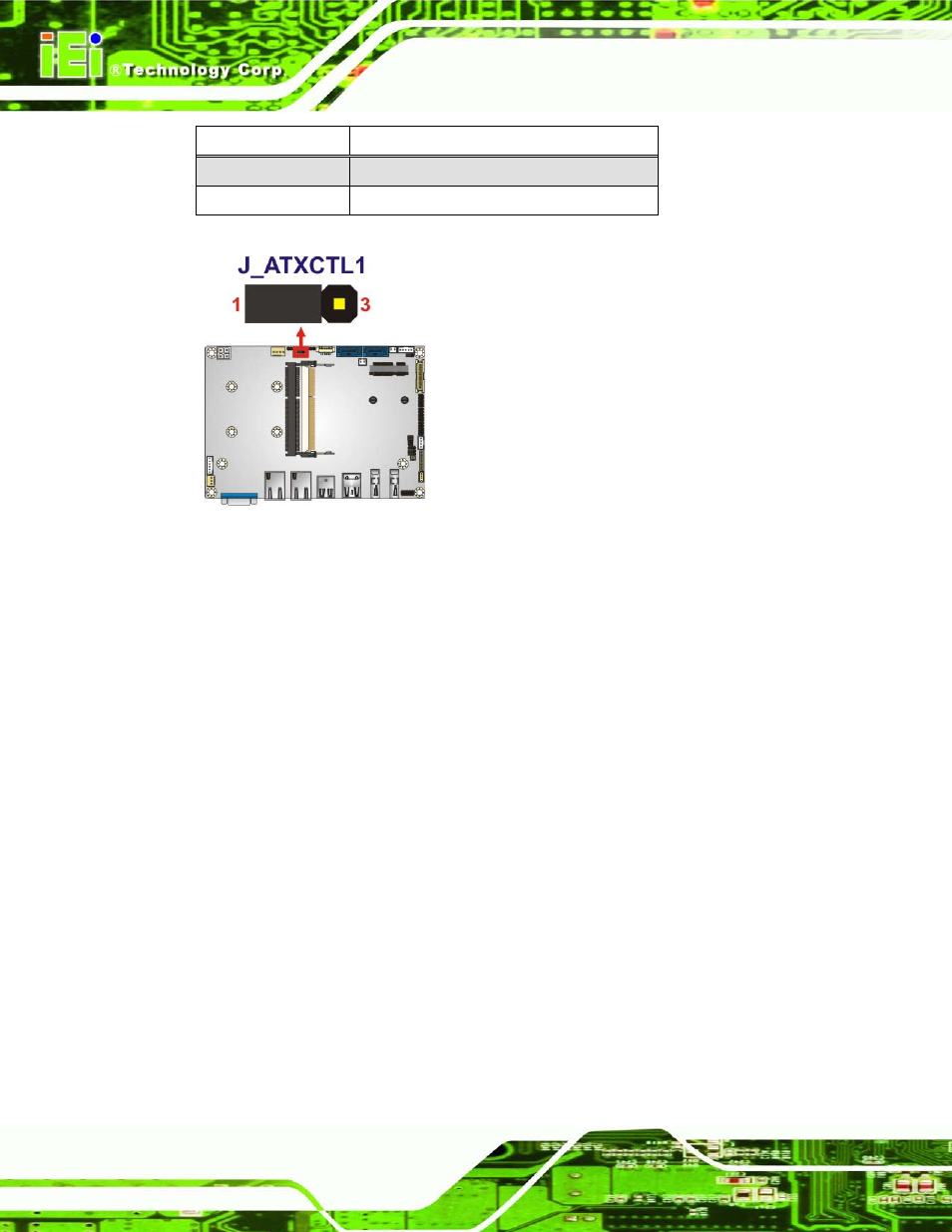
Setting
Description
Short 1-2
Use ATX power (Default)
Short 2-3
Use AT power
Table 4-29: AT/ATX Power Mode Jumper Settings
Figure 4-24: AT/ATX Power Mode Jumper Location
4.4.2 Cle a r CMOS J u m p e r
J u m p e r La b e l:
J _CMOS 1
J u m p e r Typ e :
3-pin header
J u m p e r S e ttin g s :
J u m p e r Lo c a tio n :
If the ECN-360A-HM65 fails to boot due to improper BIOS settings, the clear CMOS
jumper clears the CMOS data and resets the system BIOS information. To do this, use the
jumper cap to close pins 2 and 3 for a few seconds then reinstall the jumper clip back to
pins 1 and 2.
If the “CMOS Settings Wrong” message is displayed during the boot up process, the fault
may be corrected by pressing the F1 to enter the CMOS Setup menu. Do one of the
following:
Enter the correct CMOS setting
Load Optimal Defaults
Load Failsafe Defaults.