8 lvds backlight inverter connector, Figure 4-8: front panel connector location, Table 4-9: front panel connector pinouts – IEI Integration ECN-360A-HM65 User Manual
Page 46: Ee figure 4-8, Ee table 4-9
ECN-360A-HM65 Em b e d d e d S ys te m
P a g e 33
Reset
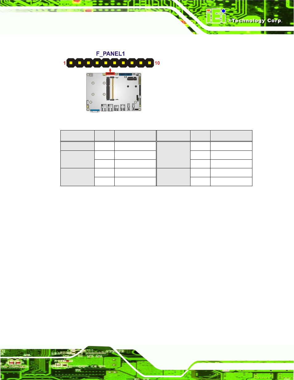
Figure 4-8: Front Panel Connector Location
FUNCTION
P IN
DES CRIP TION
FUNCTION
P IN
DES CRIP TION
1
N/A
Power LED
6
PWR_LED+
Power Button
2
PWR_BTN+
7
PWR_LED+
3
PWR_BTN-
8
PWR_LED-
HDD LED
4
HDD_LED+
Reset
9
RESET+
5
HDD_LED-
10
RESET-
Table 4-9: Front Panel Connector Pinouts
4.2.8 LVDS Ba c klig h t In ve rte r Co n n e c to r
CN La b e l:
INVERTER1
CN Typ e :
5-pin wafer (1x5)
CN Lo c a tio n :
CN P in o u ts :
The backlight inverter connector provides power to an LCD panel.
See also other documents in the category IEI Integration Computer Accessories:
- KM-088G (5 pages)
- ECW-281B_D2550 (159 pages)
- ECW-281B_B2-N270 v3.01 (189 pages)
- ECW-281B_B2-N270 v2.00 (180 pages)
- ECW-281B_B2-N270 v2.10 (179 pages)
- ECW-281B_B2-D525 (137 pages)
- IBX-530B-N270 (133 pages)
- uIBX-200-VX800 v1.04 (113 pages)
- uIBX-200-VX800 v2.00 (116 pages)
- uIBX-200-VX800 v2.10 (116 pages)
- uIBX-200 v1.02 (109 pages)
- uIBX-200 v1.10 (113 pages)
- uIBX-210-CV-N2600 (163 pages)
- TANK-101B-D525_N455 v1.02 (119 pages)
- TANK-101B-D525_N455 v1.00 (118 pages)
- TANK-101B-D525_N455 v1.10 (119 pages)
- TANK-800-D525 v1.00 (116 pages)
- TANK-800-D525 v1.14 (137 pages)
- TANK-600-D2550_N2600 (132 pages)
- TANK-GM45A (104 pages)
- TANK-700-QM67 v1.00 (128 pages)
- TANK-700-QM67 v1.12 (145 pages)
- TANK-700-QM67 v2.00 (144 pages)
- TANK-720-Q67 (147 pages)
- TANK-820-H61 v1.00 (158 pages)
- TANK-820-H61 v2.00 (158 pages)
- TANK-820-H61 v2.03 (157 pages)
- TANK-6000-C226 (138 pages)
- IDS-H61 (72 pages)
- IOPS-Q67_H61 (70 pages)
- ECN-680A-H61 (190 pages)
- ECN-780-Q67 (184 pages)
- ECN-360A-D2550 (141 pages)
- EBC-2102 (5 pages)
- ECN-581A-R10-HM551 (6 pages)
- EBC-3200 (6 pages)
- EBC-3100 (8 pages)
- EBC-3000 (7 pages)
- EBC-2100 (4 pages)
- EBC-3620 (8 pages)
- VSTAND (1 page)
- AUPS-C20 v1.01 (49 pages)
- AUPS-C20 v1.02 (55 pages)
- AUPS UART Protocal SPC (11 pages)