2 internal peripheral connectors, Table 4-1: peripheral interface connectors – IEI Integration ECN-360A-HM65 User Manual
Page 39
ECN-360A-HM65 Em b e d d e d S ys te m
P a g e 26
4.1.2 In te rn a l P e rip h e ra l Co n n e c to rs
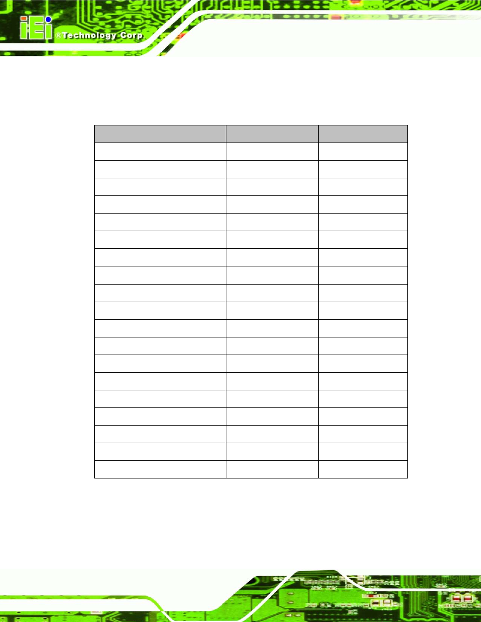
Table 4-1 shows a list of the internal peripheral connectors on the motherboard. Detailed
descriptions of these connectors can be found below.
Co n n e c to r
Typ e
La b e l
Audio connector
10-pin header
AUDIO1
Battery connector
2-pin wafer
BAT1
DDR3 SO-DIMM
204-pin SO-DIMM
DIMM1, DIMM2
Digital input/output (DIO) connector 10-pin header
DIO1
Debug port
12-pin connector
DBG_PORT1
Fan connector (CPU)
4-pin wafer
CPU_FAN1
Fan connector (system)
3-pin wafer
SYS_FAN1
Front panel connector
10-pin header
F_PANEL1
Inverter connector
5-pin wafer
INVERTER1
Keyboard and mouse connector
6-pin wafer
KB_MS1
LVDS connector
30-pin crimp
LVDS1
PCIe Mini connector
52-pin PCIe Mini slot
CN3
Power connector
4-pin connector
PWR1
SATA 6Gb/s connectors
7-pin SATA
S_ATA1, S_ATA2
SATA power connectors
2-pin wafer
CN1, CN2
Serial port connectors (RS-232)
10-pin header
COM1, COM2
Serial port connector (RS-422/485)
4-pin wafer
COM3
SMBus connector
4-pin wafer
CN4
SPI flash connector
8-pin wafer
JSPI1
Table 4-1: Peripheral Interface Connectors